Ad Widget

Collapse

Announcement

Collapse
No announcement yet.

Series Diodes w Parallel Caps

Collapse
X
 
  • Filter
  • Time
  • Show
Clear All
new posts

  • Series Diodes w Parallel Caps

    I'm confused on something and could use an explanation. I've seen this configuration in many schems, but I always figured the parallel caps were just for snubbing voltage switching transients.

    The Valve Wizard

    For the second diagram, the paragraph states
    "If diodes are used in series, a capacitor should be placed in parallel with each one, to ensure equal voltage sharing between each diode."

    I don't understand how this works. I could see it working if the caps were resistors instead, but I'm not seeing how the caps (or caps in parallel with diodes) could balance voltage.
    -Mike

  • #2
    Originally posted by defaced View Post
    I'm confused on something and could use an explanation. I've seen this configuration in many schems, but I always figured the parallel caps were just for snubbing voltage switching transients.

    The Valve Wizard

    For the second diagram, the paragraph states
    "If diodes are used in series, a capacitor should be placed in parallel with each one, to ensure equal voltage sharing between each diode."

    I don't understand how this works. I could see it working if the caps were resistors instead, but I'm not seeing how the caps (or caps in parallel with diodes) could balance voltage.
    Capacitors are impedances. They act like short-term shorts and long-term opens. If you put a step of current into a stack of capacitors, the voltage on each cap ramps up from zero to some final value. The initial ramp divides the total voltage across the stack by the inverse of the capacitances. The long term voltage is determined by the leakage resistances of the caps.

    For instance: if you have a stack of caps of values 1nF, 2nF and 3nF, and apply a current to them, then the voltage ramps up three times as fast on the 1nF as the 3nF. The 2nF is half as fast as the 1nF. This is because the three caps must share the same charge, and the voltage on a cap is the charge divided by the capacitance. In the long run, however, the current through the leakage resistances of the caps will equalize with the cap voltage, and the DC voltages long term will be what the leakage resistances say, ignoring the cap values.

    In the case of the caps in parallel with the diodes, the caps are all initially charged to the diode voltage on way, while the diodes conduct. When the voltage reverses on the diodes, the caps, presumably all being equal values, force the reverse voltage transient to be shared equally across the reverse biased diodes while the caps charge. The caps in effect overwhelm the internal junction capacitances, which might make more of the voltage appear across the lowest-capacitance diode and overstress that diode junction momentarily. With much bigger external caps, the differences in the diode junction capacitances don't matter much.

    There is a gotcha here. The cap leakages matter. The final voltage sharing is determined by the ratios of the diode leakages and the cap leakages. These are both in the range of imponderables, difficult to measure. In rectifier use, it may not matter because the applied voltage will reverse again soon enough to avoid the settling to DC voltages that could kill a diode. But in a DC situation, you could see the leakages distribute the voltage disproportionately onto one diode. In that case, parallel resistances are mandatory to force the long term DC to be shared too. Fortunately this situation doesn't happen all that often, and usually only in physics labs.
    Amazing!! Who would ever have guessed that someone who villified the evil rich people would begin happily accepting their millions in speaking fees!

    Oh, wait! That sounds familiar, somehow.

    Comment


    • #3
      Originally posted by defaced View Post
      I'm confused on something and could use an explanation. I've seen this configuration in many schems, but I always figured the parallel caps were just for snubbing voltage switching transients.

      The Valve Wizard

      For the second diagram, the paragraph states
      "If diodes are used in series, a capacitor should be placed in parallel with each one, to ensure equal voltage sharing between each diode."

      I don't understand how this works. I could see it working if the caps were resistors instead, but I'm not seeing how the caps (or caps in parallel with diodes) could balance voltage.

      It's because the page is just so badly written, I would not use it as a resource. Further, do not build a rectifier circuit with the resistors in front of the diodes as shown. The imbalance will cause the resistors to burn up. I know this because ; it did..... Lastly, the easiest way I've found to mitigate the switching transients in a diode rectifier is using the FRED diodes, which interesting enough is not shown in that page. {but I'll bet you a dollar it will just ; you know ; just "magically" appear just a few days from now}


      -g
      ______________________________________
      Gary Moore
      Moore Amplifiication
      mooreamps@hotmail.com

      Comment


      • #4
        The capacitors only balance transient voltage, if you want to balance the DC voltage then resistors are needed too.

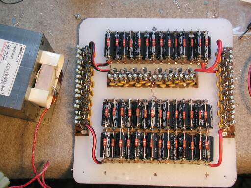
        Many years ago, I wanted to build a 10,000 volt DC supply for a high voltage project. I laboriously soldered series strings of 1N5408s with a resistor and capacitor across each one.

        After finishing this, I was told that modern diodes don't need the resistors or capacitors. They have predictable enough avalanche characteristics that they can just be hooked in series and left to fend for themselves. In other words, every 1N5408 comes with a free 1000+ volt zener that will sort of protect it, if you don't push it too hard.

        "Enzo, I see that you replied parasitic oscillations. Is that a hypothesis? Or is that your amazing metal band I should check out?"

        Comment


        • #5
          Originally posted by Steve Conner View Post
          In other words, every 1N5408 comes with a free 1000+ volt zener that will sort of protect it, if you don't push it too hard.

          ...and, your results were? Did any one of the diodes "smoke" or what?
          ...and the Devil said: "...yes, but it's a DRY heat!"

          Comment


          • #6
            Well, the power supply worked fine. I didn't test each diode individually to see if any had shorted, but since it never gave any trouble, I didn't think to test it.

            It was used to drive a Tesla coil, so it only saw short runs, maybe 10 hours of runtime total. But in a very unfriendly RF environment, so I thought lots of diode protection would be a good idea. I also used twice as many diodes as the output voltage needed.
            "Enzo, I see that you replied parasitic oscillations. Is that a hypothesis? Or is that your amazing metal band I should check out?"

            Comment


            • #7
              Originally posted by Steve Conner View Post
              Well, the power supply worked fine. I didn't test each diode individually to see if any had shorted, but since it never gave any trouble, I didn't think to test it.
              ...that was sorta my point: the "extra" protection is applied "...just in case..." the specified performance is less than promised.

              ...was that YOUR "musical" Tesla Coil that I recall seeing on the web?
              ...and the Devil said: "...yes, but it's a DRY heat!"

              Comment

              Working...
              X