Ad Widget

Collapse

Announcement

Collapse
No announcement yet.

Tube Rectifier Simulator Resistor EXPLODE!!

Collapse
X
 
  • Filter
  • Time
  • Show
Clear All
new posts

  • Tube Rectifier Simulator Resistor EXPLODE!!

    Can anyone let me know what happened here?

    This amp that I'm building is Cathode Biased 2x EL34 amp using a 125R 10W Cathode resistor (roughly 95mA of plate current per tube) with a supply voltage of 350VDC. Actual plate voltage from plate to cathode is 315VDC.

    The center tap of the B+ winding is connected to a 200R 25W resistor (that adds the compression and sag of a 5U4 rectifier tube) and the high voltage leads of the B+ are connected to a Full Wave rectifier using 2x 1N5408 diodes.

    A friend of mine was demoing the amp and he said that the amp's volume faded out after a few minutes of playing and eventually died. My first thought was that I had biased the tubes too hot which might have caused them to fail so I installed a 160R resistor in place of the 125R and tried it again. Well after playing the amp wide open the tubes died by making a bit of noise and then silence. I thought "Oh crap the tubes died!" and as soon I thought this I heard a loud POP and a huge puff of smoke only to notice that the 200R resistor had blown apart.

    What would have caused the resistor to blow? Should the B+ fuse have blown to stop this? Did the dying tubes cause the extreme current that destroyed the resistor?

    I'm really at a loss on this one. Is there anything that can be done to increase the reliability of this amp?

    Thanks so much!
    Last edited by MarshallPlexi; 11-30-2009, 06:04 PM.

  • #2
    short circuit of the B+ to ground somewhere causing the resistor to fuse out? (maybe bad tubes and/or bad filter cap(s)?)
    Building a better world (one tube amp at a time)

    "I have never had to invoke a formula to fight oscillation in a guitar amp."- Enzo

    Comment


    • #3
      See that's what creeps me out! The diodes have a fuse right after them BEFORE the OT so why on earth would the B+ fuse not blow? I need to re-check my wiring to make sure I'm not crazy here but I would swear the B+ fuse is before the first filter cap.

      When an output tube fails, what fails? Does the plate short to ground etc? What would draw this much current to blow a 25W resistor?

      Thanks!

      Comment


      • #4
        That resistor has to pass ripple current, so the RMS current through it can be about 3x the DC current. I'm guessing your DC current is normally about 140mA.
        If we are generous and say that the rms current is only 2x the DC current, that is still (2 x 0.14)^2 x 200 = 16 Watts dissipation in that resistor at idle! I'm guessing it was an aluminium clad resistor, which needs a hefty heatsink to handle its rated power. Fully dimed, the dissipation could easily exceed 30W. If it's only bolted to the chassis, there's no way it can get rid of that much heat.

        Comment


        • #5
          What size are your B+ fuses? Let's say they are 1 amp. Your B+ is 350v. That means the power supply can try to provide 350 watts without blowing that fuse. ANy circuit failures in the amp that cause it to draw less than that amount won;t blow the fuse.

          At least this was a 25W resistor - still pretty short of 350 watts, but some guys write in wondering why their fuse never blew when a 1/2W resistor burnt up inside.
          Education is what you're left with after you have forgotten what you have learned.

          Comment


          • #6
            Originally posted by Merlinb View Post
            That resistor has to pass ripple current, so the RMS current through it can be about 3x the DC current. I'm guessing your DC current is normally about 140mA.
            If we are generous and say that the rms current is only 2x the DC current, that is still (2 x 0.14)^2 x 200 = 16 Watts dissipation in that resistor at idle! I'm guessing it was an aluminium clad resistor, which needs a hefty heatsink to handle its rated power. Fully dimed, the dissipation could easily exceed 30W. If it's only bolted to the chassis, there's no way it can get rid of that much heat.
            Wow great stuff! I never even considered that! I put a 330R resistor rated at 50W last night and it seems to be working better. I also raised the Cathode resistor to a 200R 25W resistor. I used a higher value for the tube rectifier resistor to get the voltage where it was previously with the higher plate current.

            So with the 330R and the 220R the supply voltage is about 340ish with the plate voltage being about 310 and the tubes idling at about 80%. Hopefully this will make for a more stable amp.

            Comment


            • #7
              Originally posted by Enzo View Post
              What size are your B+ fuses? Let's say they are 1 amp. Your B+ is 350v. That means the power supply can try to provide 350 watts without blowing that fuse. ANy circuit failures in the amp that cause it to draw less than that amount won;t blow the fuse.

              At least this was a 25W resistor - still pretty short of 350 watts, but some guys write in wondering why their fuse never blew when a 1/2W resistor burnt up inside.
              The B+ fuse is a 1A fuse. Wow. Anything I can do to protect the circuit aside from running a much smaller value fuse?

              Comment


              • #8
                Also my previous question again. When a tube dies from over-current, which I'm assuming is what happened here, what is actually happening internally?

                Comment


                • #9
                  Fuses don;t often protect the circuit, they are there to protect your house from burning down. You can;t stick a fuse in there and expect it to prevent any/all problem(s) that can occur.

                  A variety of things can happen when a tube fails.

                  Look at a picture of a tube innards. The heater is within the cathode. Then supported around that are grids. Typicall might be a couple vertical posts with hoops of tiny wire welded to them. Then the plates are suported surrounding all that on more posts. The pates are sheets of metal.

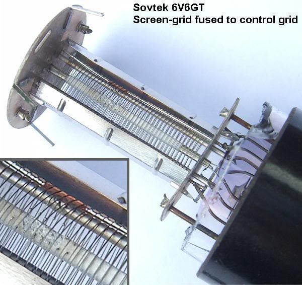
                  What goes wrong? One of those tiny wire hoops on one of the grids can break loose or melt. Ever see a light bulb that had burnt out leaving a piece of filament dangling inside? Sometimes you can shake it around so the piece of loose filament touches the other post and welds there making the light come back on. Well inside the tube, a little piece of grid wire can short to the other grids or to the plate or to the cathode or to a support post. Screens, especially on a tube like the EL34, are a common failure point. That is why a screen resistor often burns out when the tube fails. You can look in the side holes of an EL34 and see the screen grid wires glowing.

                  If the B+ on the screen grid is shorted to the control grid where the bias voltage lives, it will tend to short out the B+, but also it will swamp the bias causing the tubes to red plate.

                  If the screen grid or something shorts to the heater - and remember, all something has to do is short to a support post, it doesn;t necessarily have to get at the element itself - the hum balance parts ground off the B+. That is why the 100 ohm hum resistors burn up on a Fender when a tube fails.

                  Maybe the 450v B+ shorts to cathode. Well, cathode is grounded often as not, and that will burn up your B+ supply. B+ could short to cathode even on a cathode biased tube. That would burn out the cathode resistor quite possibly, then the 450v on the cathode are now too much for the heater to cathode space, so that shorts out and we are back to a heater short.

                  There are of course more things that can go wrong inside a tube.
                  Education is what you're left with after you have forgotten what you have learned.

                  Comment


                  • #10
                    So if the tube just completely died and a few seconds later POP!!!!!!! goes the tube rectifier resistor, then it's highly probably that the high voltage shorted to the cathode or ground thus causing a huge current draw which destroyed the resistor?

                    Comment


                    • #11
                      That is one possibility.
                      Education is what you're left with after you have forgotten what you have learned.

                      Comment


                      • #12
                        In that case what can be done to prevent tubes from dying like this? Any band-aids or will simply not running them past max plate disipation solve this?

                        Comment


                        • #13
                          Here's an example of what happens if the screen grid is allowed to draw too much current:


                          In that case what can be done to prevent tubes from dying like this? Any band-aids or will simply not running them past max plate disipation solve this?
                          In the above case, the screen resistors were too small. A 1Amp fuse it also far too large for the B+. 250mA might be more appropriate. You can also put a suitably chosen shared fuse in the cathodes of the power valve, specifically to protect those valves and the OT.

                          Comment


                          • #14
                            A 1Amp fuse it also far too large for the B+. 250mA might be more appropriate.
                            Absolutely.
                            Power dissipated in the resistor is= I(squared)xR
                            For 1A fuse: 1x1x200= 200W
                            For 0.25A fuse: 0.25x0.25x200=12.5W
                            Juan Manuel Fahey

                            Comment


                            • #15
                              Originally posted by Merlinb View Post
                              Here's an example of what happens if the screen grid is allowed to draw too much current:


                              In the above case, the screen resistors were too small. A 1Amp fuse it also far too large for the B+. 250mA might be more appropriate. You can also put a suitably chosen shared fuse in the cathodes of the power valve, specifically to protect those valves and the OT.

                              I'm using 1K 5W screen resistors on each tube. Also the amp is switchable to high power using a B+ of 450 and biasing the tubes at 38mA each. So I think you're right. A smaller fuse might save the dropping resistor.

                              As a general rule, what is the safe margin to use when selecting a fuse? In the low power mode, each tube is running at about 65mA so that times two for each tube gets us 130mA plus say about 50mA for the preamps and screens we are somewhere close to 180mA. Is a 250mA fuse too small in that it might blow during transient surges?

                              Thanks guys! This is a HUGE help!

                              Comment

                              Working...
                              X