Originally posted by Casey4s
View Post
Ad Widget
Collapse
Announcement
Collapse
No announcement yet.
Parallel 12AX7 = Boost?
Collapse
X
-
Thanks Mike I am working on all of this now.Originally posted by guitarmike2107 View PostYes, Like I said shunt the grid to ground, rather than switching the Cathode resistors.
I am going to completely re-draw this section of the schematic pretty soon, but I wan tall the problems out before I do. My CAD (Crayon Assisted Drawing) program takes a lot of room on a page LOL. I want everything on regular size paper so I can copy and scan the pages.DIY Links
Tolex Tutorial
http://www.guitarkitbuilder.com/cont...lifier-cabinet
Chassis:
http://www.guitarkitbuilder.com/cont...lifier-chassis
Turret board:
http://www.guitarkitbuilder.com/cont...d-construction
Comment
-
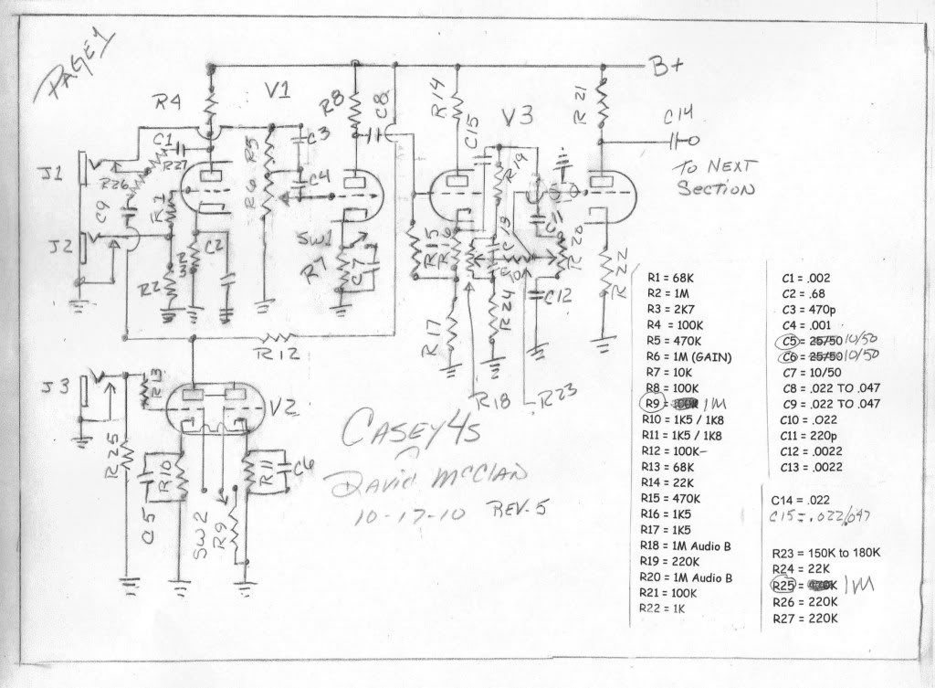
Ok, heres Revision V.
I shunted the grid of V2b to groung via 1m resistor, when not bridging the grids.
I removed the dual plate load resistors and went with a singel 47K (the liist still shows 100K)
I attached R25 to the jack with a 1M resistor
I changed the values of C5 and C6 to 10/50
 DIY Links
Tolex Tutorial
http://www.guitarkitbuilder.com/cont...lifier-cabinet
Chassis:
http://www.guitarkitbuilder.com/cont...lifier-chassis
Turret board:
http://www.guitarkitbuilder.com/cont...d-construction
Comment
-
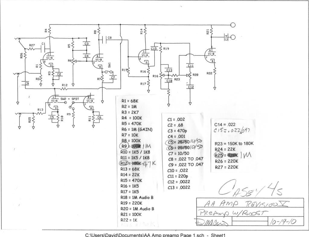
Here's my first CAD attempt. It takes me longer than drawing, but it's sure a lot neater.
 DIY Links
Tolex Tutorial
http://www.guitarkitbuilder.com/cont...lifier-cabinet
Chassis:
http://www.guitarkitbuilder.com/cont...lifier-chassis
Turret board:
http://www.guitarkitbuilder.com/cont...d-construction
Comment
-
Heres what I would start with, Just some ideas. See link below
http://www.mediafire.com/file/rc6een...st%20input.pdf
Boost switch would be a DPDT switch.
One side would switch in/out the additional triode by shunting the grid direct to ground. The 1Meg resistor is added to help prevent popping of any sort, It may not be needed or may need another value.
I would use the other side of the DPDT switch to switch in an additional cathode capacitor on the normal mode for slightly bigger bass. i.e. the boost mode will have slightly tighter (reduced) bass.
Hope that helps
Mike
Comment
-
Well now you've started with the CAD, it'll be a lot easier to change/update each schematic. And you can probably make 'macros' of various parts of the circuit by grouping certain elements together and loading them into the CAD library, so it'll make it quicker to re-draw next time.
Have you thought about how you're going to filter/supply all those triodes?
http://www.freewebs.com/valvewizard1/smoothing.htmlLast edited by tubeswell; 10-20-2010, 10:17 AM.Building a better world (one tube amp at a time)
"I have never had to invoke a formula to fight oscillation in a guitar amp."- Enzo
Comment
-
Originally posted by guitarmike2107 View PostHeres what I would start with, Just some ideas. See link below
http://www.mediafire.com/file/rc6een...st%20input.pdf
Boost switch would be a DPDT switch.
One side would switch in/out the additional triode by shunting the grid direct to ground. The 1Meg resistor is added to help prevent popping of any sort, It may not be needed or may need another value.
I would use the other side of the DPDT switch to switch in an additional cathode capacitor on the normal mode for slightly bigger bass. i.e. the boost mode will have slightly tighter (reduced) bass.
Hope that helps
Mike
Yes Mike, that helps a lot. I will ammend the drawing tomorrow and post the revision.
Thanks many times over for all your help.DIY Links
Tolex Tutorial
http://www.guitarkitbuilder.com/cont...lifier-cabinet
Chassis:
http://www.guitarkitbuilder.com/cont...lifier-chassis
Turret board:
http://www.guitarkitbuilder.com/cont...d-construction
Comment
-
Yeah I think things will be a bit easier now. I got most of the componets from "EL34" on the Hoffman forums. I actually did my power supply first, but it is not in CAD yet, so I will need to redo that as well. I used the power supply simulator at the Duncan site to set the supply up. My PT is 325 0 325 @250ma. I have about 4 more tubes (8 triodes) for the preamp, plus one for the PI.Originally posted by tubeswell View PostWell now you've started with the CAD, it'll be a lot easier to change/update each schematic. And you can probably make 'macros' of various parts of the circuit by grouping certain elements together and loading them into the CAD library, so it'll make it quicker to re-draw next time.
Have you thought about how you're going to filter/supply all those triodes?
The Valve WizardDIY Links
Tolex Tutorial
http://www.guitarkitbuilder.com/cont...lifier-cabinet
Chassis:
http://www.guitarkitbuilder.com/cont...lifier-chassis
Turret board:
http://www.guitarkitbuilder.com/cont...d-construction
Comment
-
This is revision VI.
 DIY Links
Tolex Tutorial
http://www.guitarkitbuilder.com/cont...lifier-cabinet
Chassis:
http://www.guitarkitbuilder.com/cont...lifier-chassis
Turret board:
http://www.guitarkitbuilder.com/cont...d-construction
Comment
-
Ok I will tie the cathodes together at the socket and eliminate R9. I thought R9 would help minimize poping during the switching.DIY Links
Tolex Tutorial
http://www.guitarkitbuilder.com/cont...lifier-cabinet
Chassis:
http://www.guitarkitbuilder.com/cont...lifier-chassis
Turret board:
http://www.guitarkitbuilder.com/cont...d-construction
Comment
-
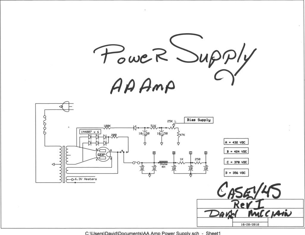
This is the whole pre amp with reverb and all. it's going to take 7, 9A type tubes, so It's a good thing my PT is rated at 250ma.

EDIT:
I just finished the power supply drawing that goes with this preamp. The rest is a pretty straight forward 2 x 5881 output section and I can probably get it all on this sheet.
 Last edited by Casey4s; 10-21-2010, 06:02 AM.DIY Links
Tolex Tutorial
http://www.guitarkitbuilder.com/cont...lifier-cabinet
Chassis:
http://www.guitarkitbuilder.com/cont...lifier-chassis
Turret board:
http://www.guitarkitbuilder.com/cont...d-construction
Comment
-
When you join up the cathodes on the input triode you only need one cathode resistor and one capacitor. Unless you plan to bias one triode differently from the other one, in which case you donít join them together.
For your power supply, you have made it switchable between the two rectifiers, but you have added a sag resistor after the diode rectifiers. I donít think you will hear much of a difference between the two like that.
Comment
-
Thanks Mike,
My original thinking was that the SS voltage should be close the same as the GZ37 going into the filtering, but I will take that out.
I will also remove the stap between the cathodes. If all else works out after the initial build, I am going to make the boost foot switchable but I didn't want to add anymore stuff to this drawing.
Thanks for the help.DIY Links
Tolex Tutorial
http://www.guitarkitbuilder.com/cont...lifier-cabinet
Chassis:
http://www.guitarkitbuilder.com/cont...lifier-chassis
Turret board:
http://www.guitarkitbuilder.com/cont...d-construction
Comment
-
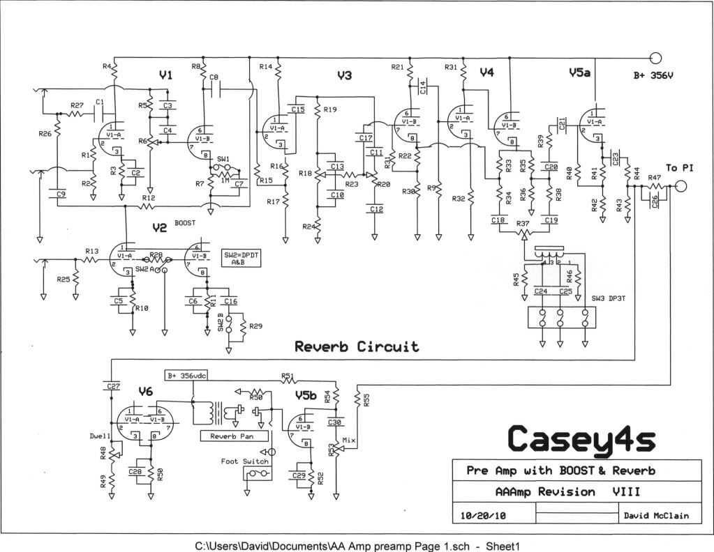
Here is the latest revision of the preamp and the power amp. I am going to enter the actual values on this drawing as soon as I am sure of a few of them, so I don't have to reference a list.
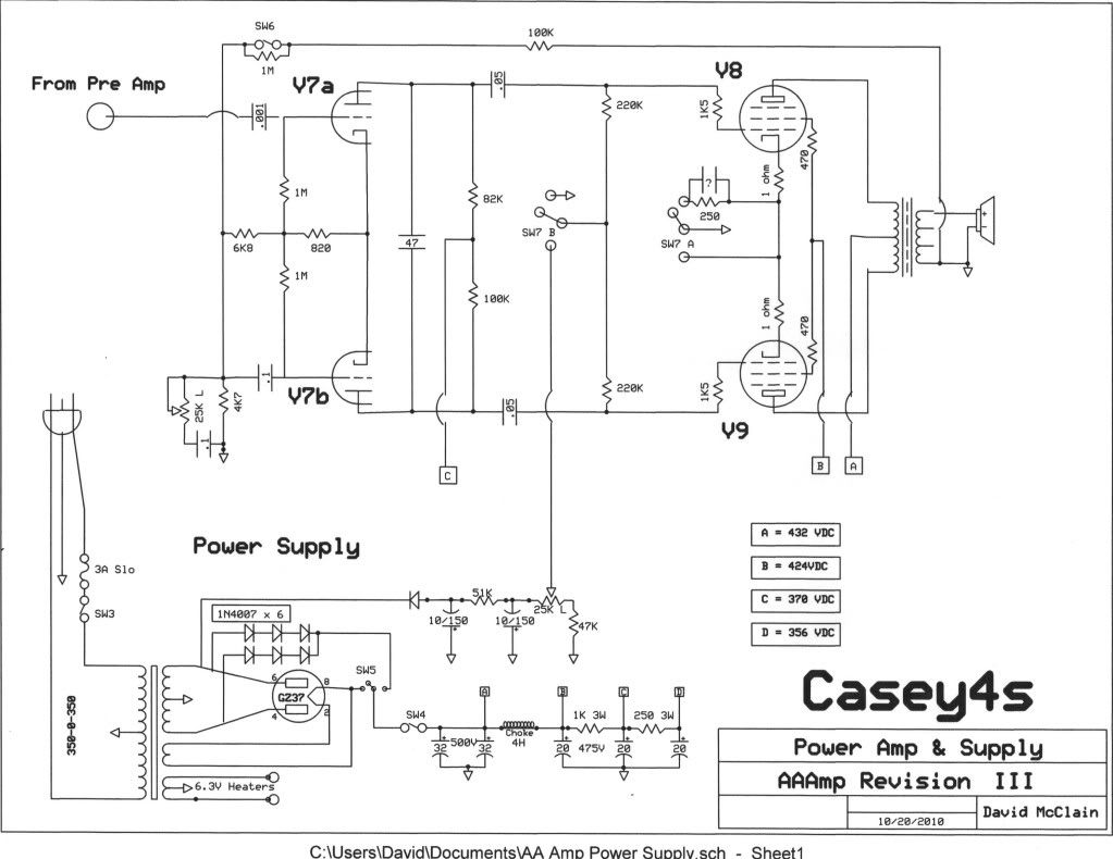 DIY Links
Tolex Tutorial
http://www.guitarkitbuilder.com/cont...lifier-cabinet
Chassis:
http://www.guitarkitbuilder.com/cont...lifier-chassis
Turret board:
http://www.guitarkitbuilder.com/cont...d-construction
Comment
Comment