Ad Widget

Collapse

Announcement

Collapse
No announcement yet.

Direct Coupling with Zener Diodes

Collapse
X
 
  • Filter
  • Time
  • Show
Clear All
new posts

  • Positive grids on 12ax7's do not amplify
    ,
    the signal is rectified.
    Both halves of the phrase, separated by a semi-colon, are not related to each other.
    Neither statement should be understood as either cause or consequence of the other.
    Is the signal rectified?
    Well, what do you mean by rectified?
    1) "the current trough the grid to cathode diode is higher when forward biased than when reverse biased", like on *any* diode in the universe. <-- agree, nothing new here.
    2) "under those conditions (forward bias, "positive grid" to comply with this post's obsession) the signal dies/hits_a_brickwall/kaputt, etc. (take your pick) meaning it dissappears or takes a fixed DC value which means it's no "signal" anymore." <-- do *NOT* agree, signal simply is attenuated (very different from dissappearing as such).
    Why is it attenuated?:
    it comes from a relatively high impedance generator, driving a grid to cathode diode, which has variable impedance: very high while reverse biased and much lower when forward biased.
    Does "much lower" mean "0"?
    Not at all.
    The grid will continue to take positive values which will be faithfully amplified by the next tube.
    Will said signal hit a brickwall some day?
    Yes, but it's not the positive grid's fault.
    Simply the earlier stage (which, by the way, is negative biased) , will either hit its own rail, or run out of current, said current being a function of the plate resistor and +B value.
    If , to throw some numbers in, the driving stage can furnish 1mA and the grid to cathode diode has an internal impedance of, say , 1K at 1 mA, 1 Volt will develop across it and will be duly amplified.
    Just like that.
    So, analysing the first half of sentence, it's *wrong*.
    Positive grids on 12AX7 *do* amplify, as predicted by physics and confirmed by datasheets and actual experiments.
    If the grid gets 1V positive, it doesn't care where it came from, it just does what grids do.
    Juan Manuel Fahey

    Comment


    • Steve, I have looked over my math, the US NAVY book and my previous experiments and I think you have proven beyond a shadow of a doubt that I am wrong. You and kg have won, thanks for documenting that.
      Peace. Out.
      Valvulados

      Comment


      • And look what just came walking through my door in a postman's hand.

        Click image for larger version

Name:	IMG_0829R.jpg
Views:	2
Size:	86.3 KB
ID:	820742

        Click image for larger version

Name:	IMG_0828R.jpg
Views:	1
Size:	88.3 KB
ID:	820743

        Lemme jump straight to direct dc coupling .."setting the bias point".... OH NO I can see it coming..."set the Rk2 so the cathode is above the grid" NOOOOOOOOOOOOOOOOOOOOOOOOOOOOOOOOOOOO
        Valvulados

        Comment


        • Again quoting random fragments fully out of context and assigning them the meaning you want.
          Not news, really.
          Juan Manuel Fahey

          Comment


          • Originally posted by J M Fahey View Post
            Again quoting random fragments fully out of context and assigning them the meaning you want.
            Not news, really.
            What the hell....I've given up already.
            Valvulados

            Comment


            • Originally posted by jmaf View Post
              And look what just came walking through my door in a postman's hand.

              [ATTACH=CONFIG]13828[/ATTACH]

              [ATTACH=CONFIG]13829[/ATTACH]

              Lemme jump straight to direct dc coupling .."setting the bias point".... OH NO I can see it coming..."set the Rk2 so the cathode is above the grid" NOOOOOOOOOOOOOOOOOOOOOOOOOOOOOOOOOOOO
              You are incredible! Now WHY do you think a CF should have it's cathode above the grid? Could it be that a CF's function is to buffer the preceding gain stage and drive a load that can be/is tougher to drive by a lone common cathode stage?

              Now let's see, if we want the CF to do it's intended job, we surely don't want the grid near or above the cathode. Why is that? Well at that point the CF becomes a difficult load for the gain stage, that would be b/c it then has a low input impedance since the grid above cathode draws electrons from the cathode and is no longer a high impedance input.

              Why does the text need to say 'keep the cathode above grid' ? Well b/c it is possible to select a Rk that draws too much current for the available Vp that the grid will go too close, or above, the cathode. How much gain will you get when the plate resistor in the gain stage is paralleled with the conducting grid of the over-biased CF?

              Haven't you even bothered to read the other posts? Have you read the article I linked to?
              I know the Navy's training is excellent for the level required for the techs, and I'm sure you are a great trouble-shooter and probably fix amps faster and better than me, and you probably even know better than me how to tune a guitar amp's response just the way a customer wants. Good on you. But you lack basic understanding in the internal operation of a tube, the basic and intermediate physics perhaps. Read the RCA manuals, read some tube books from the early days, they tend to explain in easy detail my guess b/c it was rather new science and even the professors of the day were probably still learning.

              Just stop it jmaf.

              Comment


              • redelephant, you, kg, Steve Conner and J M Fahey are in perfect agreement and on the same level of knowledge. I already conceded this discussion to you folks, you won. You are the men.
                Valvulados

                Comment


                • Originally posted by jmaf View Post
                  Lemme jump straight to direct dc coupling .."setting the bias point".... OH NO I can see it coming..."set the Rk2 so the cathode is above the grid" NOOOOOOOOOOOOOOOOOOOOOOOOOOOOOOOOOOOO
                  jmaf was just being glib to break tension guys... Let's all refill our cups and rejoin the party now.
                  "Take two placebos, works twice as well." Enzo

                  "Now get off my lawn with your silicooties and boom-chucka speakers and computers masquerading as amplifiers" Justin Thomas

                  "If you're not interested in opinions and the experience of others, why even start a thread?
                  You can't just expect consent." Helmholtz

                  Comment


                  • I learnt something too! I didn't know that the CF drew grid current in normal use until this thread. That was why I wanted to do the experiment, because I didn't quite believe it myself. It wasn't pure jmaf bashing.

                    This means a tube CF will sound different (smoother?) to a MOSFET one in the 5F6A circuit. We found another little nugget of knowledge to add to the MOSFET Follies pile, and it is all thanks to jmaf stirring s**t up.
                    "Enzo, I see that you replied parasitic oscillations. Is that a hypothesis? Or is that your amazing metal band I should check out?"

                    Comment


                    • Originally posted by Steve Conner View Post
                      I learnt something too! I didn't know that the CF drew grid current in normal use until this thread. That was why I wanted to do the experiment, because I didn't quite believe it myself. It wasn't pure jmaf bashing.

                      This means a tube CF will sound different (smoother?) to a MOSFET one in the 5F6A circuit. We found another little nugget of knowledge to add to the MOSFET Follies pile, and it is all thanks to jmaf stirring s**t up.
                      Well there you go. Next experiment: put a MOSFET in there, using the same methods you may as well find it draws current too - THAT would be Nobel prize stuff.
                      Valvulados

                      Comment


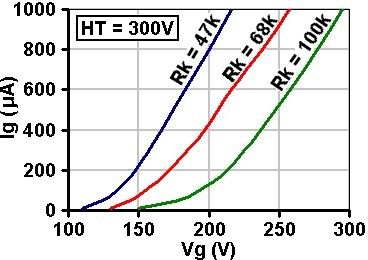
                      • Fig. 5.18 from my book shows grid current in a DC-coupled ECC83 cathode follower against grid-to-ground voltage, for different values of cathode resistor.

                        Comment


                        • Originally posted by Merlinb View Post
                          Fig. 5.18 from my book shows grid current in a DC-coupled ECC83 cathode follower against grid-to-ground voltage, for different values of cathode resistor.
                          Merlin, I could have used your book a few days ago

                          Seriously, you only humbly quoted that single graph, but going back pages and pages you have a complete treatise on grid current and its effect on the ECC83 tone.... You do mention that the Audio Engineering Society "failed to identify the quiescent grid current as the controlling factor[ of the electric guitar sound]" though.

                          I wonder why that datasheet I quoted mentions zero as the maximum grid voltage. And why the US Navy book says the grid musn't go positive, and so many other sources, including Kevin O'Connor who mentions on his text about the Schmitt long tail splitter that the grid musn't go positive....

                          In my experience, the tone of the 5F6-A circuit degrades greatly once that grid EDIT: approaches positive territory(that is my experience, not necessarily all 5F6-A's). I tested extensively after a problem I had with an amp, and found something totally different from Steve Conner, that it on the contrary does not normally draw current....and when it EDIT: approaches zero(using high output humbucker pickups instead of single coils for example), it sounded terrible, especially with pickups like seymour duncan humbuckers which seem to generate a lot of voltage. Thus, my previous erroneous conclusions that that stage must keep the grid negative at all times.

                          This is an interesting path it took, I will be reading that whole chapter soon, pencil and notebook in hand.

                          EDIT I guess I owe this to the thread. After Steve Conner's experiment and his assertion that it continues to amplify in positive territory, I have reviewed my position in this discussion, for the benefit of the doubt, and assume since he posted results and I am unable to test further now that he is right and I am wrong. I have questions still, even about his tests, but I can't fundament my questions further without investing some time in this, time I don't have now. Merlin's book has several pages on the subject, which I find most interesting, I will study them and test more. At this point, with no further data to offer for my previous assertions, all I can do is concede and move on until I am able to provide data / traces / etc to show where I got these assertions from. I have several ideas for tests, that I think would stir some more sh@#t... So...I think ....I'll be back. To those who kept this discussion in high spirit, thanks so much.
                          END EDIT
                          Last edited by jmaf; 05-09-2011, 04:12 AM. Reason: clarified my text, so it is not taken wrongly again
                          Valvulados

                          Comment


                          • This could just be my observations but it may be possible you're attributing a problem to the cathode follower that it doesn't deserve. The symptoms you described in your other thread sound more like grid blocking in one of the first two stages rather than the cathode follower.

                            I don't fully understand where you landed but I do know that it's far more likely for a coupling cap to charge up as a result of grid current than for a dc-coupled cathode follower to produce strange sounds when it draws grid current- there is no cap to charge so the second tube can't have a time constant that "shuts off" the signal. I've built a few amps with a marshall style CF driven by parallel 12ax7's or pentodes and it's easy to create grid blocking distortion. Your mileage can and will vary, of course.

                            jamie

                            Comment


                            • Originally posted by Merlinb View Post
                              Fig. 5.18 from my book shows grid current in a DC-coupled ECC83 cathode follower against grid-to-ground voltage, for different values of cathode resistor.
                              Merlin, which book is it? The original preamps one? I've resisted the urge to buy it so far, but I really want to see that treatise on the effects of ECC83 grid current that was allegedly covered up by the AES.

                              Here is one gotcha I know that might have added to the confusion. A semiconductor diode has to be biased positive before it'll conduct. But a tube diode has no such restriction. The commencement voltage for grid current can be positive, zero, or even negative, it varies between samples of the tube and even throughout the life of an individual tube.

                              So it is possible to measure a grid voltage lower than the cathode, and still have grid current flowing.
                              "Enzo, I see that you replied parasitic oscillations. Is that a hypothesis? Or is that your amazing metal band I should check out?"

                              Comment


                              • Originally posted by Steve Conner View Post
                                I learnt something too! I didn't know that the CF drew grid current in normal use until this thread. That was why I wanted to do the experiment, because I didn't quite believe it myself.
                                see, jmaf, steve wanted to prove ME wrong!

                                :lol:

                                Comment

                                gebze escort kurtköy escort maltepe escort
                                pendik escort
                                betticket istanbulbahis zbahis
                                deneme bonusu veren siteler deneme bonusu veren siteler
                                slot siteleri
                                mobile casino no deposit bonus
                                deneme bonusu veren siteler bonus veren
                                streameast
                                bonus veren siteler
                                deneme bonusu veren siteler
                                deneme bonusu veren siteler deneme bonusu veren siteler
                                bahis siteleri
                                deneme bonusu deneme bonusu veren siteler Canlı casino siteleri
                                Working...