Announcement

Collapse
No announcement yet.

Tube Rectified Amps: Standby via Switch on Rectifier Heater - Good Idea?

Collapse
X
 
  • Filter
  • Time
  • Show
Clear All
new posts

  • #61
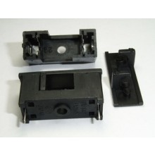
    Even though they're internal, I didn't like the idea of the conductive parts being exposed. I found this little 5x20 covered holder at Tayda:


    There aren't any real good options for PTC for the HV line, but I did decide to use them to fuse the heaters, bias winding, and the 5v supply, as they're all much smaller than even the 5x20 holders and not much more expensive than a holder + fuse. My 'protect the house, not the amp' fuse is also 5x20 and built into the IEC connector. All my amps are now IEC, whether they came that way or not - I have a cat with a penchant for chewing electrical cords. I seriously thinks she has to get a buzz from it - literally - the one below did have copper showing, and it was plugged in all the time. IEC not only makes them replaceable, but removable.

    The prince and the count always insist on tubes being healthy before they're broken

    Comment


    • #62
      Originally posted by R.G. View Post
      I do apologize for this, but it's a bit more complicated. It's common to rate tube amp PT high voltage windings in "DC output current" instead of the more common RMS of normal transformer practice. Probably the heaters are rated in AC RMS current. This is useful to someone picking a replacement transformer, but it obscures the issue with the HV DC current.

      When you rectify an AC secondary and feed that into a capacitive filter, the current feeds the cap in spikes. The spikes are quite a bit larger than the average DC current, and have a different RMS (or heating-equivalent) in the winding. That makes the transformer windings heat up more than they would with just the DC output current flowing in them. For a full wave center tap circuit like a tube rectifier setup, each half of the winding will see up to 1.2 times the DC output current, even though both are conducting. So for a transformer rated for 100ma DC output, each half-secondary for the high voltage would be protected with a slow blow fuse of about 120ma. 125ma will be OK, and may be easier to find.


      Since secondary fuses are to protect the PT, I would make them be at the rating, so that temporary transients don't cause the fuses to blow unnecessarily. So if the PT's 6.3Vac heater is rated at 3A, using a 3A fuse is not dangerous to the PT. You might use a smaller one if you're **sure** your amp will never get above your fuse but below the 3A max, but the PT is OK at 3A, so I'd use the rated current.

      If you're talking about the 5V rectifier heater winding, and the PT's 5V winding is rated at 3A I'd use a 3A fuse because people often just swap any old rectifier tube into a socket. Since the PT is OK at 3A, I'd go for 3A, since the idea is to protect the PT.


      Careful - you're mixing apples, oranges, and grenades. Fuses for protecting the PT from overcurrents, like a shorted cap, do a different thing than the series diodes. The series diodes protect the PT from a rectifier tube with an internal short. The fuse protects it against other things.
      I posted this long reply and was logged in and I forgot to copy it because for some reason before I get done and submit I am no longer logged in , don't know why.

      Well R.G. All I can do is add the diodes in case the 5Y3 blows for some reason and keep the fuse I have between the pin 8 of the 5Y3 and the B+ before all the filter caps and tubes . It is a 1/4 amp fast blow so i might need to find something smaller just to be on the safe side. No matter how small the fuse holder are I have no room to add more than the one I have now.

      If I were building an amp now I would get a chassis 25% larger and then just use the old style line fuse like fender has and put them in a row so I could access them from the outside and they would allow for a neater build because they are not solder lugs an inch apart or less but one lug above the other so one could zip tie the leads and keep it neat and away for heat. There are other types of fuse holders used on new car that are inline with the normal auto type 12 VDC fuses and the ones that use the twist lock plastic holder with the fuse inside but they are probably not built to take the heat and I am not about to test them out. Beside that those fuses for the most part go down to 1/2 amp if I recall . they may work for the heaters and 5 volt rect but the heat might kill them .

      I am not about to build another amp in this lifetime unless some lottery ticket blows in a winner or some drug deal goes bad and a suitcase full of cash was tossed through my window during their getaway.

      I just built fender amps the old way right off the schematics and layouts and can read them well enough to know how to splice the preamp section of one amp to the output of another and to make an adj fixed bias circuit or how to set the bias proper and how to get more or less gain . Mine were simple amps just like I like them without all the bell and whistles and 15 knobs and 10 switches . I got all my parts from three places and went from there. I can read a DVOM and know how to use one , I know how a tube works and can build a circuit that is quiet .

      So now I am sort of stuck , I can add the diodes in case the 5Y3 goes out and keep the fuse I have on both amps I have left between the pin 8 of the 5Y3 and the B+ before the filter caps and that's about it. I may need a smaller fuse for that since the one I have is 1/4 amp fast blow and my builds don't draw much current . Point is I just built simple amps the old way and never knew about all the protection that may be needed so I didn't plan on it. I didn't even know that the new sovtek 5Y3 was not a real 5Y3 until it came in the mail and I looked at it then questioned it then found out . So I need another NOS 5Y3 or perhaps the new JJ 5Y3 is a good bet some sell it that are reliable builders and tube supplers . I have spare matched pairs of 6V6's and preamp tubes such as 12ax7 and at7 and ay7 and lots of caps and pots and resisters and wire.

      Comment


      • #63
        If you implemented all of RG's suggestions, it would be somewhat like walking down the street covered in bubble wrap wearing 2 crash helmets. All you really need is the "house on fire" line fuse.

        Some common failure modes that can release the magic smoke are:

        Rectifier tube shorts out with pretty purple flashes.

        Worn-out power tubes go into thermal runaway and "red plate", owner doesn't realise this is abnormal and keeps using the amp until it gets bad enough to blow a fuse: if he is lucky. If he is unlucky, the excessive current burns out the PT or OT instead. This is a moderate overload over a long time period, so fuses may not pop. Best protection is a savvy owner who looks in the back occasionally to check all is well.

        Amp is cranked up with speaker disconnected, burning out the screen resistors, also possibly melting the tubes' screen grids, damaging the OT or arcing the tube sockets. "Flyback diodes", a resistor across the speaker terminals, and fusible screen resistors can all help.
        "Enzo, I see that you replied parasitic oscillations. Is that a hypothesis? Or is that your amazing metal band I should check out?"

        Comment


        • #64
          I'd say it's more like wearing a cup while fencing. It protects against something that the rules say isn't supposed to happen. Aftermarket replacement parts are available, but they lack that certain something.

          In safety analysis, most risks are evaluated against a combination of severity and likelyhood. But at the extremes of the severity spectrum, measures are sometimes taken even though the normal Severity * Likelyhood rule would otherwise contraindicate.

          Sadly, the most irreplaceable ones are also the least likely to be protected. I mean, hey - I can go buy another P-TM050 from AES for my JCM800 clone tomorrow, and it only cost me $72. Today, they still carry the same transformers I built my first amp around 18 years ago. Will it be that way in 10 years? I'd say probably. But blow the OT on your Kitchen Marshall or tweed Deluxe and you'll be crying for a long time.
          The prince and the count always insist on tubes being healthy before they're broken

          Comment


          • #65
            Besides, anything worth doing is worth overdoing. And there is never an excess of bells and whistles.
            Amazing!! Who would ever have guessed that someone who villified the evil rich people would begin happily accepting their millions in speaking fees!

            Oh, wait! That sounds familiar, somehow.

            Comment


            • #66
              Originally posted by R.G. View Post
              Besides, anything worth doing is worth overdoing. And there is never an excess of bells and whistles.
              I am still trying to figure out what I can do as far as protection . Since there are so many possible shorts that can happen and I can't possibly fit them all into my two builds without adding some sort of fuse box outside the chassis hanging on the inside the cabinet wall . All the PT leads are right at the PT so to do it right the fuses should be as close as possible . As I said before now that It's been posted here that the diodes alone are not going the protect the PT from a filter cap short . I suppose it's possible to place the diodes across the fuse holder so that way if the rect tube dies it may blow the fuse or the diode will do it's job and if a filter cap shorts the fuse will blow . I think that might work unless the diode would somehow add a path to bypass the fuse or even save the fuse . I really don't see any reason to have both . Perhaps if one did use both, the fuse would have to be right after the rect before the diode. See the problem I have with using both is that the fuse in series on either side of the diode is that the diode allows no path for current to flow through the fuse so they would have to be in parallel , diode across the fuse holder or the fuse would have to be after the pin 8 of the 5Y3 and before the B+ before the 1st filter cap and the diode in series with the HT leads and the rect tube . The diode deal is easy to do and a B+ fuse I already have as described . I don't need a flyback diode since I don't unplug my speakers ever . The weber PT I have in my champ costs about $50 shipped and the Allen Amps PT is about $100 shipped right now either would hurt the pocket but both are still available .

              Still I really wonder why not one of the main amp builders on the internet Hoffmans amps , Allen Amps, mission and Weber add this sort of protection to their offerings . Say it was a tube and the amp has a warrenty and a tube or filter cap took out the PT I would say the buyer would be out of luck especially since there is no way on earth one could prove they didn't stick the rect tube in another amp or bump it so you can't expect the tube manufacturer to cover it nor the cap manufacturer if that were the case. I had a pignose G 40V which had cheap Chinese tubes and suddenly there was a bit of smoke and volume loss but since I got the amp through one of those huge online sellers not ebay, they sent me another amp . turned out to be a screen resister on a 6L6GC that smoked I looked I saw it. So if am amp is under say a 12 month warrenty most things happen after 12 months . None of the above amp builders want unhappy customers so they must use good tubes and parts to begin with and they must know about these things that can happen . I am NOT putting anyone of them down at all , they build quality amps the old way and you can buy them without tubes if you want .

              Certainly there are many amp builders here so they can repair their own amps if need be and how long has it been known about adding all the protection . Everything I used to have as a child was tube powered TV's radios and some like a radio was over 50 years old and had a rect tube and it never went out so then you have to boil it all down to lousy modern tubes and caps . I even had an all tube stereo receiver that I got in 1966 new and it got wet moving and dropped and it still worked fine until it was stolen in 1999. We used to have a small radio repair and TV shop in a small town I used to live in, in IL had a tube tester so if something went wrong with one of my amps they had a tube testor and I got a new tube plugged it in and off I went back to normal . They were new RCA and others way back then.

              Comment


              • #67
                You can go crazy trying to prevent every possible thing that might go wrong, and you will never accomplish that. Fender amplifiers do not have a reputation for destroying their transformers all the time. Their filter caps fade away over the decades like they do in any amp. Tubes can fail at any time, but mostly they work. Power tubes naturally wear out, but in my commercial shop, I really don't have to replace all that many rectifier tubes. And the thing is as was mentioned above, rectifier tubes can fail without taking out a power transformer, in fact that is usually the case. Filter caps do short, but not very often. That failure is pretty far down my list anyways. WHy do amp makers leave out the fuses? Because they find that for the most part, they can do without. Your car has a seat belt, why don't the car makers put in full racing harness restraints?

                You are right, the diodes do not protect anything from a cap short. They protect things from a rectifier tube short.

                I don't follow your reasoning about using diodes and fuses. Put both in series between transformer and rectifier tube. The current through the fuse and diode. The diode doesn't monitor current, and th fuse doesn't monitor polarity. If the current through the winding goes excessive, as it would if a cap shorted, the fuse blows. The diode is good for 1A steady and 30A surge. (1N4007) If the rectifier tube shorts, then the diode prevents reverse polarity from getting past, and the fuse doesn't care. You do not need separate paths for each device.
                Education is what you're left with after you have forgotten what you have learned.

                Comment


                • #68
                  Originally posted by Enzo View Post
                  You can go crazy trying to prevent every possible thing that might go wrong, and you will never accomplish that. Fender amplifiers do not have a reputation for destroying their transformers all the time. Their filter caps fade away over the decades like they do in any amp. Tubes can fail at any time, but mostly they work. Power tubes naturally wear out, but in my commercial shop, I really don't have to replace all that many rectifier tubes. And the thing is as was mentioned above, rectifier tubes can fail without taking out a power transformer, in fact that is usually the case. Filter caps do short, but not very often. That failure is pretty far down my list anyways. WHy do amp makers leave out the fuses? Because they find that for the most part, they can do without. Your car has a seat belt, why don't the car makers put in full racing harness restraints?

                  You are right, the diodes do not protect anything from a cap short. They protect things from a rectifier tube short.

                  I don't follow your reasoning about using diodes and fuses. Put both in series between transformer and rectifier tube. The current through the fuse and diode. The diode doesn't monitor current, and th fuse doesn't monitor polarity. If the current through the winding goes excessive, as it would if a cap shorted, the fuse blows. The diode is good for 1A steady and 30A surge. (1N4007) If the rectifier tube shorts, then the diode prevents reverse polarity from getting past, and the fuse doesn't care. You do not need separate paths for each device.
                  My reasoning on the diodes and fuses is this . if you have a fuse in series with a diode and a diode only allows the voltage and current to flow in one direction were does the fuse see the short , it may see the positive AC but it has not reference to ground to allow it to blow with a diode in series . Perhaps I'm wrong maybe the diode works like it does in a fixed bias circuit .

                  Comment


                  • #69
                    I assume you are considering when a cap shorts. OK, so if there is a diode in series with your fuse, then conduction only happens when the positive pulses flow. If those positive pulses are shorted to ground by the shorted cap, the fuse blows. If the negative pulses are blocked from the cap, so what? They are blocked and do not get to the faulty circuit. That doesn't prevent the fuse blowinbg from the shorted positive supply.
                    Education is what you're left with after you have forgotten what you have learned.

                    Comment


                    • #70
                      Originally posted by Enzo View Post
                      I assume you are considering when a cap shorts. OK, so if there is a diode in series with your fuse, then conduction only happens when the positive pulses flow. If those positive pulses are shorted to ground by the shorted cap, the fuse blows. If the negative pulses are blocked from the cap, so what? They are blocked and do not get to the faulty circuit. That doesn't prevent the fuse blowinbg from the shorted positive supply.
                      You are right . I was only thinking of DC voltage and not AC voltage where one half of the ac from the pt HT flows through 180 from the other half since it is AC converted to DC called pulses and I was thinking PIV which is the max the diode can take before it blows not the min . I related it to the bias circuit and was wrong since the bias is not alternating current and the diode passes only one side of the PT secondary as a half wave rect and the cathode of the diode is to ground for a neg DC and also the bias cap is + to ground since it is neg voltage and the cap smooths out the ripple . I was thinking DC like when you test a diode on a meter which is a small voltage dc applied more than the .6 volts needed to pass through the diode in one direction but not the other. I just didn't think it through sorry . I do agree with you on the first part there is no way to protect everything. Certainly any tube can go at anytime and so can a cap yet if one does not maintain an amp and allows caps to sit there for decades or tubes used for years then you are asking for trouble at some point. I have had old champs 30 years old and mm bass amps as well as others that still had all the original caps and tubes and still worked fine yet that's risking it.

                      Comment

                      Working...
                      X