Ad Widget

Collapse

Announcement

Collapse
No announcement yet.

I have a long question about my P-P builds gain.

Collapse
X
 
  • Filter
  • Time
  • Show
Clear All
new posts

  • #16
    Originally posted by Diablo View Post
    Tell me about it. I've got an old Ampeg V4 that really needs to be run wide open so I can blow out the carbon from the valves. I think my wife would call 911 on me.
    So would your neighbors!!!

    My home practice amp is only twenty watts. And I prefere NOT to use the attenuator. But I do most of the time. My attenuator gets it down to about one watt. I still gets complaints from the other rooms.
    "Take two placebos, works twice as well." Enzo

    "Now get off my lawn with your silicooties and boom-chucka speakers and computers masquerading as amplifiers" Justin Thomas

    "If you're not interested in opinions and the experience of others, why even start a thread?
    You can't just expect consent." Helmholtz

    Comment


    • #17
      Originally posted by Enzo View Post
      If it helps any, I never look at the knob numbers, I just turn them until it sounds the way I want, whatever the numbers turn out to be.
      I am getting there myself . The other day I just had both the vol and tone down all the way then just hit the low E while I brought up the vol not looking then did the same with the tone.

      Comment


      • #18
        Originally posted by Chuck H View Post
        Well you would be in good company!!! I read that Stevie Ray Vaughan's tech use to remove the knobs on Stevies amps and re set them so the end adjustment would match up to where they "should" be!?!

        And FWIW I also suffer the affliction of no practice space and family close at hand. In fact my wife and I have taken in her parents as they are becoming too frail to care for themselves in all aspects. I've never played my guitar less I think I need to find a local band just so I can play my guitars and amps.
        There's nothing wrong with your expectations. Your ears will tell you when it's right for YOU. That's how artists find inspiration. Compromise and complacency are always unfortunate. Avoid them at any opportunity.
        I read that somewhere about SRV wonder if he ever turned them down and found out.

        Most of the time I just play the few acoustics I have or the pignose 7100 . My wife doesn't mind , I just get carried away a tube amp just does not quite do it set to low . I'm sure my hearing is not what it used to be when I was in a band gigging standing 6 feet away for my old super reverb cranked to 7 and getting/being old does not help much either . I sort of like the SF Champ build better in a way because it does not need to be loud to sound good. I have thought of trying the weber sig 10s ceramic in the P-P build with all the bottom that amp has it might sound fine at lower levels , that's all SF princetons had , if it does I don't really need a 12 in here. The Jensen C10R I have in the Champ build seems now to have enough bottom end since I added the 25uf bypass cap , it was enough to make it worth keeping It does the same thing if I switch out the NFB . I can tell if I flip the bypass cap switch back to normal 2uf . I want to try the other 12ax7's I have in it. the JJ 12ax7 is darker sounding but the sovtek had a nicer vib to them , maybe with the added 25 uf they my just right. I was looking at the fender product site and they use the jensen C10R in their BF princeton reverb RI model and looking at the specs they say it's a 40 speaker when it's not.

        Comment


        • #19
          Originally posted by Chuck H View Post
          +++

          catnine, try this, add a 100k resistor between the PI input grid and the 1M dropper. This is supposed to reduce the odd distortions characteristic of cathodyne PI's. You can go a bit higher if you think it made an improvement. If this stops the bad sounding distortion then at least we've eliminated one problem without the need of a scope. But understand that without a scope this is all going to be like shooting in the dark.
          So far all I did was swap tubes. First I removed the 12ax7 in V2 and installed a 12at7 . At that point the amp didn't sound different all it did was allow me to bring the vol up from 4 1/2 to 6 1/2 before the breakup set in . Then I left the 12at7 in V2 and changed the 12ay7 in V1 to a 12ax7 . It didn't really change the sound much but it changed the point of breakup to about 5 1/2 on the vol pot. It seems the 12at7 makes the most difference overall. There was a subtle change in tone in the bass yet it was really difficult to tell. The treb seemed to a bit more pronounced with the 12ax7 in V1 and the bass was a bit more focused. Yet with a bit of a turn on the tone pot I could bring it back to pretty much the same as with the 12ay7 in V1.

          If I switched out the second gain bypass cap and added the NFB loop the gain is less no matter if i use a 12ax7 or 12at7 in V2 yet if I raise the vol level 2 numbers up the vol level is about the same with the bypass cap and no NFB , however the bass nots are tighter and the breakup is smoother but if I use a 12ax7 in V1 then the breakup seems to hit that raspy sound, this was not the case if I had the NFB off and V2's bypass cap in. So I can see how the preamp affects the second gain and how the second gain affects the preamp.

          I did notice that with the 12at7 in V2 the breakup was not quite so raspy as with the 12ax7, it was more smooth this was either with the 12ax7 or 12ay7 in V1.

          Like I said the 12at7 in V2 seems overall to make the most difference. I am not sure why the breakup is more raspy with the 12ax7 in V1 with the V2's bypass cap out and the NFB on. It's really difficult to tell it seems to sound best with the 12ay7 in V1 and 12at7 in V2. Once I get near 7 on the vol the amp is very loud . It's difficult to tell because by the time I change tubes I sort of forget how it sounded before . The main difference is the vol setting which means nothing but the less raspy breakup means a lot. If I just turn the vol pot a tiny bit down on any strat the buzz goes away. I don't get this with my Champ build. It may be the larger OT I can't say. I keep thinking it may be because I have the switch that switches out the V2 bypass cap and add;s the NFB is right next to the input jacks so I have a output lead right next to the inputs.

          Another thing I did notice even before the tube change is with any one of my 3 strats if I stand next to the amp it seemed quiet , I used a long cord from the guitar to the amp and seemed like the further away I moved this buzz I get was worse but if I put the strat behind the wall it was gone so it must be typical strat buzz, none of my strats have shielded cavities.

          I think a 12ay7 draws more current that a 12ax7 so since the plate on the 12ay7 is 151 VDC on a 12ax7 it may be higher. I'm not just about the 12at7.

          Comment


          • #20
            Wow.!. I need to be somewhere tonight, but I need to go over this post with multiple quotes and responses as soon as I can.
            "Take two placebos, works twice as well." Enzo

            "Now get off my lawn with your silicooties and boom-chucka speakers and computers masquerading as amplifiers" Justin Thomas

            "If you're not interested in opinions and the experience of others, why even start a thread?
            You can't just expect consent." Helmholtz

            Comment


            • #21
              Originally posted by catnine View Post
              So far all I did was swap tubes. First I removed the 12ax7 in V2 and installed a 12at7 . At that point the amp didn't sound different all it did was allow me to bring the vol up from 4 1/2 to 6 1/2 before the breakup set in . Then I left the 12at7 in V2 and changed the 12ay7 in V1 to a 12ax7 . It didn't really change the sound much but it changed the point of breakup to about 5 1/2 on the vol pot. It seems the 12at7 makes the most difference overall. There was a subtle change in tone in the bass yet it was really difficult to tell. The treb seemed to a bit more pronounced with the 12ax7 in V1 and the bass was a bit more focused. Yet with a bit of a turn on the tone pot I could bring it back to pretty much the same as with the 12ay7 in V1.
              What you did, more than change the tone of the amp, was change the gain structure. With the AT7 in V2 and an AX7 in V1 you gave the amp more audible preamp distortion before power tube clipping.

              To be certain, any change in headroom with this tube swap has been in the wrong direction. Even though the volume knob is at a higher setting before clipping the actual watts out before clipping has either NOT changed or may actually have been reduced.

              Originally posted by catnine View Post
              If I switched out the second gain bypass cap and added the NFB loop the gain is less no matter if i use a 12ax7 or 12at7 in V2 yet if I raise the vol level 2 numbers up the vol level is about the same with the bypass cap and no NFB , however the bass nots are tighter and the breakup is smoother
              With the preamp tube change you are probably hearing more preamp clipping. Which is class A and therefor not prone to crossover issues. The greater amount of NFB is certainly why the bottom end is tighter.


              Originally posted by catnine View Post
              but if I use a 12ax7 in V1 then the breakup seems to hit that raspy sound, this was not the case if I had the NFB off and V2's bypass cap in. So I can see how the preamp affects the second gain and how the second gain affects the preamp.
              Wait!?! I thought you DID have a 12ax7 in V1!?!

              I'm not sure what the scenario is that I'm reading here.

              Originally posted by catnine View Post
              I did notice that with the 12at7 in V2 the breakup was not quite so raspy as with the 12ax7, it was more smooth this was either with the 12ax7 or 12ay7 in V1.
              OK.. Back to something I'm clear on. I think there is a limit to how much voltage drive you can put into the cathodyne before it sounds crappy. It may also be that the AT7 handles the cathodyne duties better than the AX7. But the reality is that either tube operates about the same as a cathodyne inverter in your circuit. The more significant change, IMHO, is the amount of voltage driving the cathodyne. Which is reduced when the AT7 is used as V2. The grid stop resistor I suggested should help more WRT the bad effect you hear when the cathodyne is overdriven.

              Originally posted by catnine View Post
              Like I said the 12at7 in V2 seems overall to make the most difference. I am not sure why the breakup is more raspy with the 12ax7 in V1 with the V2's bypass cap out and the NFB on.
              Because 1) Your hearing more preamp distortion.
              2) NFB can excacerbate crossover distortions.
              3) Removing a bypass cap from a preamp stage flattens the gain/frequency relationship. And raspy sounds are actually more often due to excess LF rather than HF when clipping is involved. So by removing the bypass cap and raising the gain (via the use of a higher gain tube OR turning up the volume knob) you've actually increased the level of LF in your clipped signal.

              Originally posted by catnine View Post
              It's really difficult to tell it seems to sound best with the 12ay7 in V1 and 12at7 in V2. Once I get near 7 on the vol the amp is very loud . It's difficult to tell because by the time I change tubes I sort of forget how it sounded before . The main difference is the vol setting which means nothing but the less raspy breakup means a lot. If I just turn the vol pot a tiny bit down on any strat the buzz goes away. I don't get this with my Champ build.
              It is difficult to be clear on tonal differences with tube swaps. Lot's of things come into play. Time, temperature, mood, etc. A switch is the best way to test tonal differences. Which is almost impossible WRT tube swaps.

              The raspy tone is likely to be either your perception of preamp distortion (rather than power tube distortion) since you've likely increased the preamp to power amp clipping ratio with the tube swap. Or it could be the additional LF in the preamp. Or it could be crossover distortion. Which would explain why you don't have the same problem with your Champ.

              Originally posted by catnine View Post
              It may be the larger OT I can't say. I keep thinking it may be because I have the switch that switches out the V2 bypass cap and add;s the NFB is right next to the input jacks so I have a output lead right next to the inputs.
              Well now!!! That could be the whole thing right there. Perhaps reducing V2 gain is helping stabilize the amp by reducing gain in an oscillation prone environment.

              Originally posted by catnine View Post
              Another thing I did notice even before the tube change is with any one of my 3 strats if I stand next to the amp it seemed quiet , I used a long cord from the guitar to the amp and seemed like the further away I moved this buzz I get was worse but if I put the strat behind the wall it was gone so it must be typical strat buzz, none of my strats have shielded cavities.
              So this "buzz" isn't tone related, but strictly background noise?

              Originally posted by catnine View Post
              I think a 12ay7 draws more current that a 12ax7 so since the plate on the 12ay7 is 151 VDC on a 12ax7 it may be higher. I'm not just about the 12at7.
              That's a very good observation. The difference might be really small. I've never actually checked when plugging AY7's into AX7 circuits. But if the voltage is higher with the AX7 that could contribute to a harsher (or stiffer, brighter) tone. But I think this is probably a small matter in the big picture right now.

              You should definitely try the grid stopper on the PI input. And then retest with tube swaps, etc. Also, anything that can be done to change the amps layout so the output isn't sharing space with the input is almost certain to help. In fact, the input/output proximity amd the NFB lead could be a big part of the problem.
              "Take two placebos, works twice as well." Enzo

              "Now get off my lawn with your silicooties and boom-chucka speakers and computers masquerading as amplifiers" Justin Thomas

              "If you're not interested in opinions and the experience of others, why even start a thread?
              You can't just expect consent." Helmholtz

              Comment


              • #22
                Originally posted by Chuck H View Post
                What you did, more than change the tone of the amp, was change the gain structure. With the AT7 in V2 and an AX7 in V1 you gave the amp more audible preamp distortion before power tube clipping.

                To be certain, any change in headroom with this tube swap has been in the wrong direction. Even though the volume knob is at a higher setting before clipping the actual watts out before clipping has either NOT changed or may actually have been reduced.


                With the preamp tube change you are probably hearing more preamp clipping. Which is class A and therefor not prone to crossover issues. The greater amount of NFB is certainly why the bottom end is tighter.


                Wait!?! I thought you DID have a 12ax7 in V1!?!

                I'm not sure what the scenario is that I'm reading here.


                OK.. Back to something I'm clear on. I think there is a limit to how much voltage drive you can put into the cathodyne before it sounds crappy. It may also be that the AT7 handles the cathodyne duties better than the AX7. But the reality is that either tube operates about the same as a cathodyne inverter in your circuit. The more significant change, IMHO, is the amount of voltage driving the cathodyne. Which is reduced when the AT7 is used as V2. The grid stop resistor I suggested should help more WRT the bad effect you hear when the cathodyne is overdriven.


                Because 1) Your hearing more preamp distortion.
                2) NFB can excacerbate crossover distortions.
                3) Removing a bypass cap from a preamp stage flattens the gain/frequency relationship. And raspy sounds are actually more often due to excess LF rather than HF when clipping is involved. So by removing the bypass cap and raising the gain (via the use of a higher gain tube OR turning up the volume knob) you've actually increased the level of LF in your clipped signal.


                It is difficult to be clear on tonal differences with tube swaps. Lot's of things come into play. Time, temperature, mood, etc. A switch is the best way to test tonal differences. Which is almost impossible WRT tube swaps.

                The raspy tone is likely to be either your perception of preamp distortion (rather than power tube distortion) since you've likely increased the preamp to power amp clipping ratio with the tube swap. Or it could be the additional LF in the preamp. Or it could be crossover distortion. Which would explain why you don't have the same problem with your Champ.


                Well now!!! That could be the whole thing right there. Perhaps reducing V2 gain is helping stabilize the amp by reducing gain in an oscillation prone environment.


                So this "buzz" isn't tone related, but strictly background noise?


                That's a very good observation. The difference might be really small. I've never actually checked when plugging AY7's into AX7 circuits. But if the voltage is higher with the AX7 that could contribute to a harsher (or stiffer, brighter) tone. But I think this is probably a small matter in the big picture right now.

                You should definitely try the grid stopper on the PI input. And then retest with tube swaps, etc. Also, anything that can be done to change the amps layout so the output isn't sharing space with the input is almost certain to help. In fact, the input/output proximity amd the NFB lead could be a big part of the problem.
                The buzz I hear seems to be background noise , I just don't hear it with the champ at least it doen't stand out where I notice it. But it only happens with the guitar plugged in and as I said if I back off a bit on the guitar vol it goes away so it has to be background noise and I suppose since this amps OT is so much larger than the champ there is possibly a much larger magnetic field .

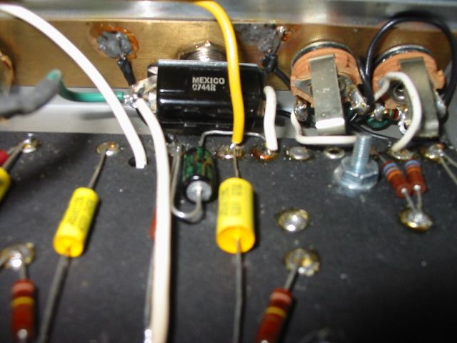
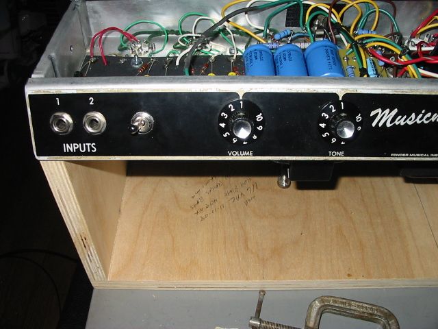
                The second photo in the origninal post shows the NFB switch , on the far left the green lead is the NFB coming from the output jacks , on the right is the two input jacks and just left of them is the switch where you can see the back of the switch , also you can see how I moved the 25uf cap + side to the switch so there is also the + side of the cap right there when it used to be on the other side of the eyelet board across the 1.5K cathode bias resister where there is now a white lead through the switch to make that connection. I did this in 09 and never really played the amp all that much after that change . It just cought my attention when I looked at the photo and it is an output singal right next to the input , not a good idea. To add , the only bypass cap I switch out is the second gain before the PI I don't have a switch for V1 bypass cap that is always in circuit.

                I like the idea of the switch so I will have to move it to the rear of the chassis but V1 is still the input so I need to fine a spot as far to the right of V1 as possible or closer to the actual output jacks. Looking at the full chassis photo you can see the out put jackes are between the two output tubes yet that is the output end so maybe that's the best spot or perhaps closer to V2 where there is more room . If not then I can just wire it back and not have NFB since the chassis is so crammed . I do know on my Champ build the NFB switch is between the V1 and output jack and there is no issue .

                Just to be clear the 12ay7 was in V1 most of the time when I put the 12at7 in V2 . I only tired a 12ax7 in V1 just to see how it affected things , a test of sorts. I will keep the 12ay7 in V1 . Add the 100K grid stopper to the grid of the PI triode and move or remove the NFB loop then see how it reacts.

                I am not sure of the 12at7 in V2 it has to be biased different that the 12ax7 in V2 . I can rebias the second gain stage of V2 if needed but I don't see a way of rebiasing the PI and then I'm not certain what values would center bias a 12at7 compared to a 12ax7 or it it really matters.

                I found this www.thetubestore.com - Gain Factor but this refers to preamp tube swaps yet it talks about how certain preamp tubes drive the OT section harder. Can't say if this applies to a PI or second gain stage.

                It seems that the 12ax7 in V2 is what the circuit was designed for not a 12at7 and since a 12at7 draws more mA than a 12ax7 , perhaps it's best to stick with a tube designed for a circuit and that's what fender used other than 12at7's in LTP but that's not the same as a split load now is it? I was told I should add a switch to V1 to remove the bypass cap there to reduce gain in half . Like you said before I don't know which stage is overdriving the amp to create the OD sound that is harsh . All I do know it is much smoother with the 12at7 since it has a lower gain than a 12ax7 so my gut tells me it's the PI gain that produces to OD grit I don't like becasue so far that's what makes the most diff . I read the grid stopper resister on the PI grid on Valve Wizard. He claims it makes an astounding diff.

                Comment


                • #23
                  Originally posted by catnine View Post
                  The buzz I hear seems to be background noise , I just don't hear it with the champ at least it doen't stand out where I notice it. But it only happens with the guitar plugged in and as I said if I back off a bit on the guitar vol it goes away so it has to be background noise and I suppose since this amps OT is so much larger than the champ there is possibly a much larger magnetic field .
                  Background noise that is guitar dependent is going to be a matter of gain and volume. Are the two amps being used at the same levels for sensitivity and volume? That doesn't seem likely. The OT proximity isn't likely an issue if you're more than three feet from the amp. And I think a bigger OT dissapating the same power as a smaller OT would have the same amount of magnetic field. Possibly less?

                  Originally posted by catnine View Post
                  The second photo in the origninal post shows the NFB switch , on the far left the green lead is the NFB coming from the output jacks , on the right is the two input jacks and just left of them is the switch where you can see the back of the switch , also you can see how I moved the 25uf cap + side to the switch so there is also the + side of the cap right there when it used to be on the other side of the eyelet board across the 1.5K cathode bias resister where there is now a white lead through the switch to make that connection. I did this in 09 and never really played the amp all that much after that change . It just cought my attention when I looked at the photo and it is an output singal right next to the input , not a good idea. To add , the only bypass cap I switch out is the second gain before the PI I don't have a switch for V1 bypass cap that is always in circuit.
                  That should be a well attenuated output signal. If moving that lead around changes things I would re-route it. Otherwise I don't think your layout is very problematic, though I can't see everything. Including where your OT is mounted.

                  Originally posted by catnine View Post
                  I like the idea of the switch so I will have to move it to the rear of the chassis but V1 is still the input so I need to fine a spot as far to the right of V1 as possible or closer to the actual output jacks. Looking at the full chassis photo you can see the out put jackes are between the two output tubes yet that is the output end so maybe that's the best spot or perhaps closer to V2 where there is more room . If not then I can just wire it back and not have NFB since the chassis is so crammed . I do know on my Champ build the NFB switch is between the V1 and output jack and there is no issue .
                  Try the switch in the alternate position and routing without actually mounting it. If it helps with anything, mount it in the new location.

                  Originally posted by catnine View Post
                  Just to be clear the 12ay7 was in V1 most of the time when I put the 12at7 in V2 . I only tired a 12ax7 in V1 just to see how it affected things , a test of sorts. I will keep the 12ay7 in V1 . Add the 100K grid stopper to the grid of the PI triode and move or remove the NFB loop then see how it reacts.
                  Right. The grid stopper on the PI is sorta the point. If the sheer gain driving the PI is the problem (as with a 12ax7 in V2 instead of the 12at7) you might find the grid stopper stabilizes things such that you can put the 12ax7 back into V2. All you need to do is put a resistor at the end of the PI input lead to find out.

                  Originally posted by catnine View Post
                  I am not sure of the 12at7 in V2 it has to be biased different that the 12ax7 in V2 . I can rebias the second gain stage of V2 if needed but I don't see a way of rebiasing the PI and then I'm not certain what values would center bias a 12at7 compared to a 12ax7 or it it really matters.
                  The difference will be small. Even differences betwen tubes of the same designation will skew from center bias a tad up or down. You shouldn't need to change the cathode resistor every time you change a preamp tube. Don't sweat it. Biasing the PI should really be done with a scope since cathodynes have some funny behaviors depending on how their driven. It's hard, for me, to just do it by numbers. I need to see in all operating conditions to know I'm getting the best performance.

                  Originally posted by catnine View Post
                  I found this www.thetubestore.com - Gain Factor but this refers to preamp tube swaps yet it talks about how certain preamp tubes drive the OT section harder. Can't say if this applies to a PI or second gain stage.
                  Well sure it does. Gain structure and how hard a follwing stage is driven compared to it's output capability is something we need to get a handle on when targeting a specific tone, effect, headroom, etc.

                  Originally posted by catnine View Post
                  It seems that the 12ax7 in V2 is what the circuit was designed for not a 12at7 and since a 12at7 draws more mA than a 12ax7 , perhaps it's best to stick with a tube designed for a circuit and that's what fender used other than 12at7's in LTP but that's not the same as a split load now is it?
                  You can use the 12at7 as V2 with no problems if it sounds better to you. But DO try adding the grid stopper to the PI and listen to both tube types in V2 before moving on.

                  Originally posted by catnine View Post
                  I was told I should add a switch to V1 to remove the bypass cap there to reduce gain in half . Like you said before I don't know which stage is overdriving the amp to create the OD sound that is harsh . All I do know it is much smoother with the 12at7 since it has a lower gain than a 12ax7 so my gut tells me it's the PI gain that produces to OD grit I don't like becasue so far that's what makes the most diff . I read the grid stopper resister on the PI grid on Valve Wizard. He claims it makes an astounding diff.
                  Did I mention trying a grid stopper on the PI?
                  "Take two placebos, works twice as well." Enzo

                  "Now get off my lawn with your silicooties and boom-chucka speakers and computers masquerading as amplifiers" Justin Thomas

                  "If you're not interested in opinions and the experience of others, why even start a thread?
                  You can't just expect consent." Helmholtz

                  Comment


                  • #24
                    Originally posted by Chuck H View Post
                    Background noise that is guitar dependent is going to be a matter of gain and volume. Are the two amps being used at the same levels for sensitivity and volume? That doesn't seem likely. The OT proximity isn't likely an issue if you're more than three feet from the amp. And I think a bigger OT dissapating the same power as a smaller OT would have the same amount of magnetic field. Possibly less?

                    That should be a well attenuated output signal. If moving that lead around changes things I would re-route it. Otherwise I don't think your layout is very problematic, though I can't see everything. Including where your OT is mounted.

                    Try the switch in the alternate position and routing without actually mounting it. If it helps with anything, mount it in the new location.


                    Right. The grid stopper on the PI is sorta the point. If the sheer gain driving the PI is the problem (as with a 12ax7 in V2 instead of the 12at7) you might find the grid stopper stabilizes things such that you can put the 12ax7 back into V2. All you need to do is put a resistor at the end of the PI input lead to find out.


                    The difference will be small. Even differences betwen tubes of the same designation will skew from center bias a tad up or down. You shouldn't need to change the cathode resistor every time you change a preamp tube. Don't sweat it. Biasing the PI should really be done with a scope since cathodynes have some funny behaviors depending on how their driven. It's hard, for me, to just do it by numbers. I need to see in all operating conditions to know I'm getting the best performance.


                    Well sure it does. Gain structure and how hard a follwing stage is driven compared to it's output capability is something we need to get a handle on when targeting a specific tone, effect, headroom, etc.


                    You can use the 12at7 as V2 with no problems if it sounds better to you. But DO try adding the grid stopper to the PI and listen to both tube types in V2 before moving on.


                    Did I mention trying a grid stopper on the PI?
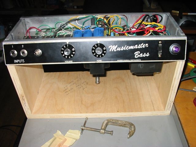
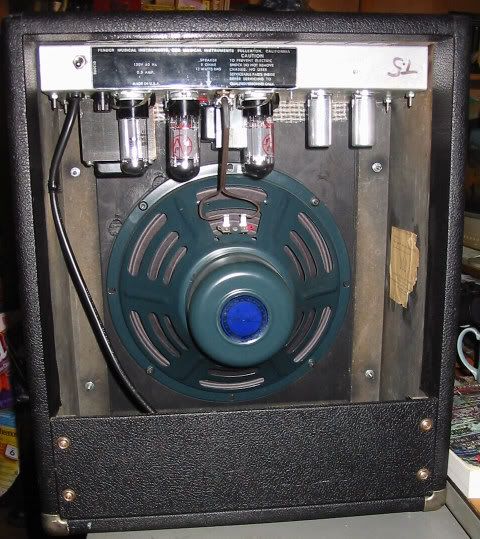
                    here is a photo of the back chassis showing were the OT is.


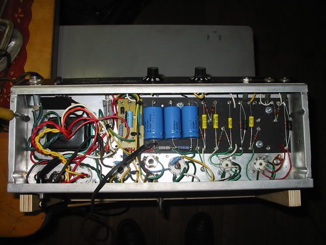
                    This is the full inside chassis view before the switch was added .


                    The two output tubes as seen in the full chassis photo are right between the output tube sockets , one jack is more to the rear of the chassis . The Ot's center looking inside the chassis would be centered with the first filter cap and the OT is close to the front of the chassis.
                    .
                    Here is a better shot of the switch. The white lead dropping down goes from the vol pot wiper to pin 2 grid of V2 , the yellow lead comes from the wiper of the tone pot to the outter lug of the vol pot through the .02uf coupling cap connected to a 100K plate resister to pin 6 plate of V1

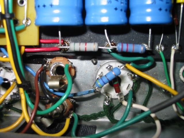
                    here you can see the green lead bottom right the NFB lead and the output jacks.

                    this shows the OT and also the green lead high above the chassis running to the switch.It has black heat shrink over the NFB resister.

                    a closer shot


                    I wanted to add , last time I checked the voltages I did check pin 7 the grid on V2 for the PI and had 21.9 VDC that was with the 12ax7 .
                    Last edited by catnine; 01-21-2013, 12:18 AM.

                    Comment


                    • #25
                      Your layout situation doesn't seem that bad. It may be that the phase of any near-er proximity is opposing. That would affect the tone but wouldn't cause instability. Which you don't seem to have. The voltage on pin 7 V2 doesn't mean much to me because I don't have other voltages to reference it to. So it's sort of arbitrary by itself. You should start with a grid stopper at the PI input and see how that affects performance.
                      "Take two placebos, works twice as well." Enzo

                      "Now get off my lawn with your silicooties and boom-chucka speakers and computers masquerading as amplifiers" Justin Thomas

                      "If you're not interested in opinions and the experience of others, why even start a thread?
                      You can't just expect consent." Helmholtz

                      Comment


                      • #26
                        Originally posted by Chuck H View Post
                        Your layout situation doesn't seem that bad. It may be that the phase of any near-er proximity is opposing. That would affect the tone but wouldn't cause instability. Which you don't seem to have. The voltage on pin 7 V2 doesn't mean much to me because I don't have other voltages to reference it to. So it's sort of arbitrary by itself. You should start with a grid stopper at the PI input and see how that affects performance.
                        I understand all of what you are saying . What I don't get is the amp is right now just like a fender 6G2 same values across the board just higher voltages . I have a few sound clips people who have 6G2's sent to me and they don't have that raspy breakup they don't have the PI grid resister. Not saying I won't try it just that i don't understand it . What it seems to do is keep the PI grid from to much grid voltage injected from the plate of the second gain. The 6G2 has a 12ax7 for the preamp and I use a 12ay7 I would think that alone would lower the gain fed into the second gain then the PI grid. Of course the voltages listed on many of the fender schematics are not exact and each one can be different . Do you think it's possible I am looking at gain the wrong way when describing raspy breakup? Could it just be the speaker that breakups up in a way I don't like . I don't recall this rasp sound when I used higher watt 12" ceramic speakers and the 6G2 only used a 10" speaker some of the old Oxfords were alnico 10's and they didn't have this rasp sound that I can hear.

                        Comment


                        • #27
                          Very likely... I found the speaker and OPT have much larger influences on the sound than the tubes or circuit topologies, so unless you are using the same speakers/OPT like your friend, the amps could sound very different. I think there is only so much you can do to tweak the component values... You may well lose some of the other characterstics that you like about your amp after you gotten rid of the raspiness, so compromises have to be made at some point. I have not read through all the posts, but if you know the B+ is too high, why not lower it to "spec"? Sorry if it has already been covered...

                          Comment


                          • #28
                            Yesterday I pulled the chassis just to see how the switch next to the input jacks affected the amp . I removed the NFB lead off the output jack first which seemed logical . Once I did that I powered up the amp and notinced that when the second gain stage bypass cap was in circuit I had that buzz I had before with nothing plugged in the inputs.

                            Since the side of the switch where the bypass cap was connnected was closest to the input jacks it seems that it was interfering somehow , if I switched it to the now disconnected NFB side of the switch it was quiet .

                            Before going further I checked the voltages on V2 with the 12at7 in . pin 1 147 pin 3 2.26 pin 6 217 Pin 7 read between the 1 meg and 56K 71.5 pin 8 73.7. before with the 12ax7 in V2 12ax7 ---- 208 1.57 254 54.1 65.1

                            Then I added a 1.5K ohm grid resister on the PI grid . I decided to move the switch to the rear of the amps chassis and rewired it and all the buzz was gone NFB in or out Bypass cap in or out . The NFB lead is 2" long now and the pos side of the bypass cap is close to where it should be on the eyelet board rather than sitting on the neg side near the inputs .

                            The next thing I did was check every resister and found the 1.5K that comes off the cathode for the PI was 1.887K this resister is where the 1 meg and 1.5K and 56K meet. I had a 1K which is what all P-P princetons use so I used that. Put the 12ax7 back in place instead of the 12at7 pin 1 207 pin 3 1.54 pin 6 246 pin 7 junction of the 1 meg and 56K 62.9 pin 8 64.1 .

                            I haven't had a chance to play it since it's to late in the day but at least the buzz is gone. I don't know what I was thinking putting a 1.5K on the grid of the PI it was 100K I should have started with so I was not thinking clear . Now I need to go back and change that . I just realized that while typing this. And I put the chassis back in the cab thinking I was done for now. I read somewhere some use 1 meg there , I don't understand how the resister does not affect the 1 meg already there other than the .02 cap is on the junction with the 1 meg and the wire to pin 7 of V2 . I pulled the chassis again and all I had was a 1 meg so I pulled out the 1.5 K and installed the 1 meg as the PI grid stopper.

                            It seemed at times still with nothing plugged in if I turned vol pot up and down I would hear an old noise something like motorboating but not loud but then it would just go away . Also the 12ay7 is a EH tube in V1 I never really played around with this before but if the chassis is out of the cab with the vol up if I even touch the input lead I get a buzz if is not there unless I have the amp past 4 or if I touch the chassis . But if I have the chassis in the cab and I turn up the volume if I tap the 12ay7 it hear it also if I tap the chassis I hear it. The more I bring up the vol the more I can hear this like microphonic tube. All I have is a 12ax7 to see if that does the same thing. I never heard it playing through the amp but then I never turn the vol up that high. I can't say if putting the 1 meg on the V2 grid has anything to do with any of this I never fooled around with the amp this way before so I can't say . ie , I never tapped on the tubes or let it sit on for as long with nothing plugged in or raised and lowered the vol just to see if anything would happen had no reason to.
                            Last edited by catnine; 01-24-2013, 04:30 AM.

                            Comment

                            Working...
                            X