Ad Widget

Collapse

Announcement

Collapse
No announcement yet.

LTPI tweaking

Collapse
X
 
  • Filter
  • Time
  • Show
Clear All
new posts

  • #16
    [QUOTE=NateS;340434]Ok, here's my analysis of the stock preamp, 100mV input, volume at 35% (linear), master cranked, and TMB at 5-5-5. (It doesn't look like anything close to 10db loss)
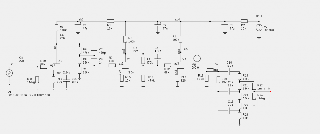


    I don't see how you get 140V at the output at pi_in!!!! This is a typical circuit I use also. The output of X4 is about 150Vpp max for aa3 at 225V. The tone stack attenuates at least half even with treble and mid cranked up. and then you have the divider of R22 and R24, so you have only about 30V best case at the pi_in. I got into problem because I use it at treble and mid at half. It is divided by 3 just on the tone stack. I got only 50V out of the junction between R14 and R21.

    In fact I scoped the points from ak4 to pi_in point to point. Are you based on simulation or real measurement?
    Last edited by Alan0354; 03-24-2014, 04:46 AM.

    Comment


    • #17
      Originally posted by NateS View Post
      The phase inverter starts clipping around 8vpp IIRC. Are you sure its clipping before the phase inverter, and not in the phase inverter?

      And by mixing stage - I was thinking about a local feedback inverting mosfet summing amp.
      Not with the circuit you posted!!! You have very low gain with the large R9 and R10. You should have more than 8V input range for the differential pair.

      Comment


      • #18
        Of course it doesn't clip with an almost unity gain stage. The stock inverter seems to clip about that point though. I was quite surprised by that. If you're seeing 150vpp measured at the cathode output, that's a nice sanity check on the sim, and means everything up to the tone stack is spot on. The divider is the master volume, drawn with two resistors for simulation purposes. It ignores any loading by the phase inverter, but thanks to negative feedback, the phase inverter is much less of a load than the master volume. A simple RC tone stack is also not a place I'd suspect simulation to fall apart, not unless there's some heinous flaw in the sim itself (like spice's case insensitivity and the milli/Mega trap which waits for newbies). I even moved my test frequency up to 400Hz hoping to take advantage of the bigger loss seen in the AC analysis above.
        The prince and the count always insist on tubes being healthy before they're broken

        Comment


        • #19
          I think the tone stack is where the big loss. I just tested the clean channel with a similar tone stack, attenuation is about half too with everything at full. It is consistent on both. At typical setting for playing, the attenuation is down to 1/3. I don't have the solid data from the pass, but I could swear the loss is in the ball park.

          Yes, for a normal differential pair that has gain of about 40 to 50, it clips about 5 to 7V.

          One more note, even the sine wave is not clip at the output of the cathode, but it is obviously flattened in asymmetrical way when it reach close to the max on both channels. The 100K pull down resistor is running out of steam already.

          Comment


          • #20
            Originally posted by NateS View Post
            Ok, here's my analysis of the stock preamp, 100mV input, volume at 35% (linear), master cranked, and TMB at 5-5-5. (It doesn't look like anything close to 10db loss)
            Perhaps the average loss isn't 10dB, but still a large portion get awfully close, AND the question was how to get 140Vp-p at the PI's input, i.e., after the tonestack. If you want to have Class A2 drive, then LPT with 12AX7 probably won't do the job, but don't take my word for it, breadboard it and see for yourself.

            Comment


            • #21
              Originally posted by NateS View Post
              It doesn't look like floating paraphrase buys me anything much, two triodes and still has a ton of gain I need to trade away.
              The FP usually has a gain of 50 or so but I was thinking it could be converted to ‘unity gain’ by making both sides unity gain inverting amplifiers then it would be able to take the 140V p-p input and give 140V p-p output as the circuit below.

              Click image for larger version

Name:	FPPId.gif
Views:	1
Size:	15.5 KB
ID:	832862
              Last edited by Dave H; 03-25-2014, 09:23 PM.

              Comment


              • #22
                Yeah, I've been playing with local feedback, I didn't try without the CCS because once the idea occurred to me, I started trying to maximize the intrinsic gain and use feedback around the stage rather than source resistor feedback.

                I actually had the crazy idea of building an active EQ (ala Simple, Easy Parametric and Graphic EQ's, Plus Peaks and Notches) / summing amp / phase inverter in one stage, since I have this differential amp and feedback around it. But it seems to seriously imbalance the outputs in the frequency domain. The differential amp is almost magical in what you can do with it - it's almost an analog computer, but I don't think you can use it for differential input, differential output, and do anything too funky with the inputs without unbalancing the outputs.
                The prince and the count always insist on tubes being healthy before they're broken

                Comment


                • #23
                  Originally posted by NateS View Post
                  Yeah, I've been playing with local feedback, I didn't try without the CCS because once the idea occurred to me, I started trying to maximize the intrinsic gain and use feedback around the stage rather than source resistor feedback.

                  I actually had the crazy idea of building an active EQ (ala Simple, Easy Parametric and Graphic EQ's, Plus Peaks and Notches) / summing amp / phase inverter in one stage, since I have this differential amp and feedback around it. But it seems to seriously imbalance the outputs in the frequency domain. The differential amp is almost magical in what you can do with it - it's almost an analog computer, but I don't think you can use it for differential input, differential output, and do anything too funky with the inputs without unbalancing the outputs.
                  You can surely use it as differential input. Problem is you have 47K at the tail that make it not working in a lot of cases. If you remove the 47K, you don't need CCS at all. The way people keep it constant current is to use the feedback to the bottom of the tail and move the bottom up and down with the signal to keep the current constant.

                  You still have not reply my question. At this point, I am very sure that you have attenuation of 1/2 from the tone stack, You cannot get more than 60Vpp out of the tone stack. Then you put a resistor on top of the MV pot, you can further divide the signal down, you get say 30Vpp. With NFB of power amp, you can use any traditional differential amp design. Seems like you are going in a circle. What you show is a circuit being used by many famous amp and almost everyone tinkering with high gain channel using this. I don't think anyone have problem with too much signal from the preamp.

                  I am working on a very similar circuit like yours, it cannot be I have to work to get the amplitude up and you have to make the gain of the differential pair down to 1!!!! It is just not possible as I have my hands on my amp hours a day right now!!!! My problem is I have two channel, I loss signal due to the mixing( summing ) action. But it's so easy for you to put a resistor on top of the MV pot to divide down half and you'll have about 20V output. Set the NFB of the power amp lower and you match everything.

                  Even when I open the NFB loop, it is still ok!!!! We have a big big disconnect here.

                  What you want is hard to get, you want input range of 150V and output range of over 100V and a gain of 1. You rule out a lot of tube circuit for no good reason. Simple unity gain differential output using a triode with equal cathode and plate resistor that is commonly used in guitar amp, cannot be used with your requirement!!!
                  Last edited by Alan0354; 03-25-2014, 10:47 PM.

                  Comment


                  • #24
                    Originally posted by Alan0354 View Post
                    You can surely use it as differential input. Problem is you have 47K at the tail that make it not working in a lot of cases. If you remove the 47K,
                    Originally posted by Alan0354 View Post
                    You still have not reply my question. At this point, I am very sure that you have attenuation of 1/2 from the tone stack, you put a resistor on top of the MV pot...You rule out a lot of tube circuit for no good reason.
                    1) Sorry - I'm jumping around quite a bit in discussion relative to circuits I've actually posted. I'll try to be more linear here, lest this degenerate into argument.

                    2) I'm not able to breadboard this until I get a large chunk of uninterrupted free time. Since I have a toddler in the house... you'll just have to be patient.

                    3) I'm not even planning to build anything until the sim works, or I have a good answer for why the simulation is inadequate. I know a lot of old timers like to gripe about simulations, and I get the reasons but... I'm not about to go build something that I couldn't get working in simulation. If I want pain and frustration for no good reason, there are cheaper ways that waste less time.

                    4) There is no extra resistor ahead of the master volume. The Master volume is represented in that schematic by two resistors, because SPICE doesn't understand potentiomenters, it only knows resistors. The junction of the "two resistors" is the wiper. And in any case,it's cranked wide open in the circuit I posted. 1 milliohm/wiper/1Megaohm.

                    5) I have my own good reasons why I wanted to try a solid state phase inverter. Namely, I don't LIKE phase inverter distortion. Of the four triode stages in the 2204 preamp, only two of them actually distort. I have a TL072 input stage right at the jack that duplicates the 1st stage pre-emphasis and gain pretty closely, and with lower resistor values in the signal path. All a tube phase inverter does for me is suck down heater current, add microphonics, and get replaced once in a while.
                    The prince and the count always insist on tubes being healthy before they're broken

                    Comment


                    • #25
                      Originally posted by Alan0354 View Post
                      ...What you want is hard to get, you want input range of 150V and output range of over 100V and a gain of 1.
                      The circuit I posted will do that easily but whether it’s desirable to do it is a different question. What do you do if you want output stage negative feedback for example? Feedback could be returned to the summing junction of the input triode but with a unity gain PI there isn’t enough gain for it to be effective. The excess preamp gain exists to generate the distortion/tone. I’d just attenuate it to the level required by the power amp at the PI input.

                      Comment


                      • #26
                        Originally posted by NateS View Post
                        1) Sorry - I'm jumping around quite a bit in discussion relative to circuits I've actually posted. I'll try to be more linear here, lest this degenerate into argument.

                        2) I'm not able to breadboard this until I get a large chunk of uninterrupted free time. Since I have a toddler in the house... you'll just have to be patient.

                        3) I'm not even planning to build anything until the sim works, or I have a good answer for why the simulation is inadequate. I know a lot of old timers like to gripe about simulations, and I get the reasons but... I'm not about to go build something that I couldn't get working in simulation. If I want pain and frustration for no good reason, there are cheaper ways that waste less time.

                        4) There is no extra resistor ahead of the master volume. The Master volume is represented in that schematic by two resistors, because SPICE doesn't understand potentiomenters, it only knows resistors. The junction of the "two resistors" is the wiper. And in any case,it's cranked wide open in the circuit I posted. 1 milliohm/wiper/1Megaohm.

                        5) I have my own good reasons why I wanted to try a solid state phase inverter. Namely, I don't LIKE phase inverter distortion. Of the four triode stages in the 2204 preamp, only two of them actually distort. I have a TL072 input stage right at the jack that duplicates the 1st stage pre-emphasis and gain pretty closely, and with lower resistor values in the signal path. All a tube phase inverter does for me is suck down heater current, add microphonics, and get replaced once in a while.
                        So you are saying that the circuit you posted is not the circuit you are using? Then it's a completely different story.

                        I do a lot of simulations using LTspice and Microwave Office. Actually I am quite new in this tube amp stuff. Solid state, opamp and transistors are really what I used for design for decades as an engineer. BUT I do have two of the tone stack stages very close to what yours and I can tell you that the tone stack attenuates the signal by at least 1/2. And at practical setting, the attenuation is 1/3. This is just real measurement. You really need to check you simulation, I don't know what else to tell you. I tripled check with scope, sweeping frequency before I posted.

                        Oh yeh, you can use N-MOSFET to substitute the tubes and it will work quite similar. Whether you get the sound or not is another thing. In fact, it looks like you can use depletion mode MOSFET to substitude all the tubes in tube amp with change of bias resistors.
                        Last edited by Alan0354; 03-26-2014, 12:27 AM.

                        Comment


                        • #27
                          Originally posted by Dave H View Post
                          The circuit I posted will do that easily but whether it’s desirable to do it is a different question. What do you do if you want output stage negative feedback for example? Feedback could be returned to the summing junction of the input triode but with a unity gain PI there isn’t enough gain for it to be effective. The excess preamp gain exists to generate the distortion/tone. I’d just attenuate it to the level required by the power amp at the PI input.

                          Yes, your circuit should work. I did not even look as I think what OP's original schematic do not have excessive voltage swing at the output. There is a difference between his simulation and the real circuit as I described. I don't even want to get into the unity gain differential stuff until that clears up. What OP posted is a basic circuit used by a lot of people and nobody have issue of excessive preamp output, and it's not.

                          Comment


                          • #28
                            Ok, I got the windows emulator back out so I could run Duncan's TSC, which is widely accepted. The Fender TS does indeed have a 20-25db insertion loss at the notch, but the Marshall stack at 100Hz, which was my test frequency, with a 1 Meg volume and 2Meg PI input impedance is only -5db down. Since the cathode follower can swing 150V and that's been verified, -5db from 150vpp is 85vpp. I then measured my guitar open A string once it settled in after the pick transient and it looks like 50mV is a bit more realistic than 100mV. With the input voltage and output load set correctly, my sim shows about 75vpp, which is close enough the figure above that I'm willing to believe it.

                            I think I can live with +10db of gain in the phase inverter, that would approximately match the common mode gain of the existing phase inverter, where the NFB input is traditionally routed, and use local feedback around the stage rather than getting all my feedback from the source resistors.
                            The prince and the count always insist on tubes being healthy before they're broken

                            Comment


                            • #29
                              Then if you are willing to throw away a little more putting a resistor on top of the MV pot, you are right into the zone already.


                              BTW, I did not get 150Vpp swing at plate voltage of 182V. I raise ab4 to 375V to get 215V at aa3 (the plate voltage) to get barely 150V. I did lower to 185V and the swing was only about 120Vpp.

                              Also, there is nothing wrong to over drive the power amp a little. In my setup, I match the preamp to power amp so I do make the power amp clip some at the max to get the power amp distortion. So that gives you more room to increase the gain of the differential PI. I would guess about 4 to 6dB extra. So from your calculation of +10dB. You gain 4dB with a resistor divider, 6 db to over drive the power amp. You can now use a differential pair with gain of 10dB+4dB+6dB=20dB......which is gain of 10!!! This is easy to implement now.
                              Last edited by Alan0354; 03-26-2014, 05:27 AM.

                              Comment


                              • #30
                                A source follower can get quite a bit closer to the rails. I'm all for overdriving the power tubes. I'm just trying to avoid clipping the phase inverter in the process, since it's mosfet.
                                The prince and the count always insist on tubes being healthy before they're broken

                                Comment

                                Working...
                                X