Ad Widget

Collapse

Announcement

Collapse
No announcement yet.

Rectifying Heater Voltage and Voltage Doubler?

Collapse
X
 
  • Filter
  • Time
  • Show
Clear All
new posts

  • Rectifying Heater Voltage and Voltage Doubler?

    OK, I have an amp that has a faceplate that I want to light up with LED's. I need about 15 VDC. My heater circuit has no center tap but uses two 100 ohm resistors to form one. Can someone point me to a voltage doubler circuit that will work with my heater set up without affecting the 6.3VAC for the tubes? Everything is already wired up so I don't want to change over to DC heaters. Thanks!

    Dave

  • #2
    You don't actually need 15V to light Leds up.
    6.3V rectified will give you roughly 7V DC ; Red Leds need 1.9V each plus a series resistor to limit current.
    2 Red Leds in series need 3.8V and series 220 ohms will give you around 15mA per pair.
    Use as many pairs as you wish, and adjust voltage and series resistor to match colour.
    10/15 mA per diode is a good compromise between brightness and long life.
    The diodes do not need to be grounded at any end, just strung across rectified DC which will measure close to +/- 3.5V respect to ground, if filaments have some kind of centertap.
    Juan Manuel Fahey

    Comment


    • #3
      Juan,

      Thanks. Yeah, I thought about lowering the series resistors. I have 4 yellow LED's in parallel, each with an 820 ohm series resistor. I'm getting about 8.7 VDC with a full wave rectifier (two diodes) unloaded. They aren't bright enough. Powering them with 18 volts on a battery does the trick. I thought raising the voltage was the way to go. Guess I'll try lowering the resistors.

      Dave

      Comment


      • #4
        Usually, for outdoor lighting applications, they use 4 ultra bright white LEDs in series and a bridge rectifier on a 12vac transformer. For 6vac I assume you could use 2 in series and parallel them up as much as you want. I'm rebuilding all of my outdoor fixtures that way using dollar store flashlights, lol.

        Comment


        • #5
          Originally posted by Daver View Post
          Juan,

          I'm getting about 8.7 VDC with a full wave rectifier (two diodes) unloaded.
          Can you post a schematic? I can't see how you can get 8.7 VDC from a 6.3V heater winding with a 2 x 100R 'centre tap' and a two diode full wave rectifier.

          Comment


          • #6
            Well, now with all the tubes in, I'm getting 4.1 volts DC. So I'm back to my original question; what kind of voltage double can I use? Thanks.

            Comment


            • #7
              If you don't have any filter capacitance after the rectifier, you might just be reading the average DC which is only about 63% of the peak of a rectified sine wave. The LEDs don't need any filtering but they will strobe at 120Hz. Might look strange on video.
              WARNING! Musical Instrument amplifiers contain lethal voltages and can retain them even when unplugged. Refer service to qualified personnel.
              REMEMBER: Everybody knows that smokin' ain't allowed in school !

              Comment


              • #8
                I have a 1,000uf cap after the diodes for filtering. The AC heater voltage under load is 6.1 volts.

                Comment


                • #9
                  You should have (6.1*1.4)-2=6.5V DC, even under heavy load (1A which means 20/30 very bright LEDs).
                  Remember this is a floating voltage, so measure across capacitor legs and ground none of them.

                  And Led brightness depends on current, not voltage, so proper way is to decrease resistance, not rise voltage.

                  And regular Leds are very cheesy, I *always* pay for high efficiency ones, 20X to 50X brighter than bargain bag or generic ones.

                  I have used these for over 15 years: 5mm, 20mA, crystal clear lens (undyed) , most Leds light output are measured in milli-candles ; these are measured in full candles, such as 1.4CD or 2.8CD (or 1400 to 2800 mCD which is the same).
                  L-53SRC-E - KINGBRIGHT - LED, 5MM, RED, 2.8CD, 640NM | Farnell element14


                  to boot, the crystal lens ones concentrate light where you want it


                  They are part of my brand image, Musicians go see other bands playing live, see these fierce red/orange shining onstage and say "hey !!!! , they are using a Fahey !!!! " .... all for the princely sum of 30 to 50 cents each.
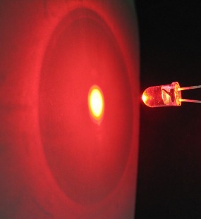
                  Here it's seen outside the central cone of light, even so stronger and more defined than a standard LED, and this is a flash illuminated pictures, where all Leds look turned off, but here:


                  I also add them to amps modded by me (say, a Marshall JCM900 where I junk the old PCB and place one of my boards, keeping cabinet, chassis and iron), marketing results are the same, I "must" show possible customers that this is not a run of the mill Marshall but something special, notice the red/orange light on the Marshall head to the left of my Daughter's head, seen from 40 yards away, in broad daylight:


                  Some Christian customers call them "the light/eye of God" , go figure.
                  All these are examples of a single LED, passing some 30mA .

                  Search Mouser for high intensity Leds in the colour you like, then order results by light intensity or mCD value, then balance output to price, your choice.

                  I only use regular Leds for clipping, go figure.
                  I guess I'm spoiled.

                  So try to get (way) better LEDs

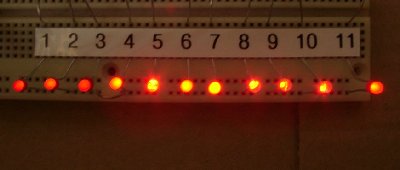
                  These are all passing the exact same current ... are different types of course.
                  Juan Manuel Fahey

                  Comment


                  • #10
                    Thanks for that, Juan. Well I only have 4.1 volts. It's not a full wave bridge, just a full wave rectifier. I agree there should be more. Is the artificial center tap screwing things up?
                    Last edited by Daver; 10-10-2015, 11:41 PM.

                    Comment


                    • #11
                      Originally posted by Daver View Post
                      ...It's not a full wave bridge, just a full wave rectifier...
                      You need a center tap to support a full wave rectifier and your first post says that you do not have a center tap. Can you post a diagram of the circuit you wired up? I'm guessing that you may have ended up with a half wave rectifier with an extra diode drop. That would explain the low voltage.

                      Comment


                      • #12
                        Full wave? tell me, are you using this with a diode from each end of the 6v winding with grounded CT, and a filter from the diodes to ground? In that case, you are rectifying 6v CT or 3.15vAC twice. That rectifies and filters to 4.45vDC, and subtract for diode drop and you are close to that 4.1v. I think Juan mentioned that LEDs don't have to be grounded. So if you just put a bridge across the two ends, with no ground connection, you should get closer to 7vDC. Not to ground, but across the supply.


                        You want to do an experiment? Start with your voltage source, then grab a 1k or 5k pot and wire it like a variable resistor in series with the LED across that voltage. Now dial in the brightness you like. Then disconnect it all and measure the resistance the pot is set to. There is your resistor value. Use a standard value resistor that is close.
                        Education is what you're left with after you have forgotten what you have learned.

                        Comment


                        • #13
                          Bingo, Enzo. I have a virtual center tap with two 100 ohm resistors and one of things I was wondering about was how that was affecting things. I've decided to abandon using the heaters and wired up a half wave rectifier using the secondary AC, like some bias supplies, only positive. Then I can juggle the resistors to get the voltage I need. Thanks!

                          Comment


                          • #14
                            The heater supply is your best option. Dropping 50 or 60 Volts from a bias winding is not practical. Just use a full wave bridge and let the LEDs ( and series resistor ) float across the output of the bridge. Do not connect either side to ground.
                            Last edited by loudthud; 10-11-2015, 02:03 AM. Reason: Simul post
                            WARNING! Musical Instrument amplifiers contain lethal voltages and can retain them even when unplugged. Refer service to qualified personnel.
                            REMEMBER: Everybody knows that smokin' ain't allowed in school !

                            Comment


                            • #15
                              Did you understand the part about rectifying the whole 6v, rather than the two halves of it? You were creating a supply referenced to ground. My suggestion is a floating supply. The LEDs are not part of the audio and do not care about being ground referenced. Connect the AC corners of the bridge to the ends of the 6v, then the + and - corners of the bridge are your new supply. No ground connection involved.

                              It was mentioned earlier, the voltage is not what you need to change. yes, if you are stuck with a particular value resistor, then changing the voltage changes the current. But generally in LED circuits, we start already knowing the voltage across the LED itself, and we know the power supply voltage. So we calculate the resistor value to cause the desired CURRENT through the LED.

                              I usually light LEDs with 10ma, which is PLENTY. Typical LEDs in my drawer have like a 20ma max. 5-10ma lights them up nice. 10ma is simple math. Let's say I have a blue LED with 2v forward voltage drop. (I made that up, but the data sheet for any LEd tells its forward voltage.) And let us say I have a 12v DC supply. That means I have to drop 10 of those volts to leave the 2v across the LED. So my resistor drops the 10v. Now with a 2v LED and a 12v supply, I will have 10v across most any resistor I choose. But current is constant in a series circuit, so if I set the resistor to have 10ma current through it, then the LED will also have 10ma through it. So in my example, I need the resistor to drop 10v at 10ma current. Ohm's Law tells us: volts = current times resistance. Solving for resistance, R = V/I SO 10v/0.01A = 1000 ohms. If I wanted 5ma, then 10v/0.005A = 2000 ohms.


                              The experiment I described is simple. But I have been using arbitrary current numbers. Take the LEDs you want to use, and connect a variable resistor (a potentiometer) in series with one, and power this with a 9v battery. Dial in the amount of brightness you think is good. Measure the voltage across the LED just for the record, but mainly measure the voltage across the resistance of the pot. Now use Ohm's Law to calculate the current at the brightness you like.

                              Now you can power the LED from most any voltage you like, but this CURRENT you calculated should be the target. If 10ma current from the 9v battery lights the LED to your liking, then 10ma will make it the same brightness regardless of the voltage you start with. The power supply voltage and resistor value set the current.


                              yes, if you have a bias winding, you can rectify it for positive alongside the negative bias supply. You will then have something like 50v. So you would need a much larger resistor. But it will work.
                              Education is what you're left with after you have forgotten what you have learned.

                              Comment

                              Working...
                              X