 Tweet
Tweet
Hi all,
this is a nice little amp with a particular (and new for me) reverb circuit.
I was helping a friend to re-cap it during the lockdown using videocalls and making shopping lists together on Mouser.
Somehow he's lost the REVERB in the process (it worked when he bought the amp) and now I have the amp with me and trying to bring it back to life.
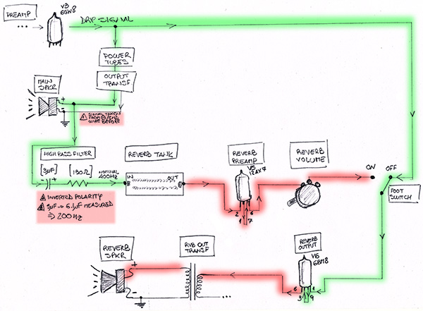
Here is the SCHEMATIC
What's new for me is that the AUDIO SIGNAL that feeds the REVERB circuit is coming from one of the wires going from the OUTPUT TRANSFORMER to the MAIN SPEAKER and that the unit has a DEDICATED REVERB SPEAKER (smaller) which also plays the DRY signal when the REVERB is OFF.
I've been following the signal path in two ways:
- CIRCUIT as in the SCHEMATIC:
first there were a few wiring issues that I corrected
- the REVERB feed signal was being taken from the NEGATIVE SPKR wire (which is also connected to ground). So there was no signal. Actually the speaker connector to the circuit was inverted.
- The electrolytic capacitor polarity was replaced with a new one and the polarity was inverted
additionally:
- the value of the e-cap is not the 3 uF indicated on the schmatic (the closer we could get was 5 uF wich actually measures 6.1 uF). So the frequency is cut below 200 Hz instead of 400 Hz as intended originally (but I guess this is more a matter of taste than a potential functional problem)
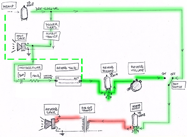
Here I see that:
- the REVERB SIGNAL is lost after the REVERB TANK INPUT
- the DRY signal is lost after when trying to come out of the V6 tube Pin 6
- Feeding signal to the REVERB TANK OUT
to check the rest of the circuit after the REVERB TANK
the schematic is missing any reference voltages other than the HV right after all the big capacitors so I am not sure of what voltages to expect at the REVERB TANK (I guess some is needed to drive the transducers unless they are driven only by the magnet) or at the 6BM8 V6 tube.
6BM8 V6 tube VOLTAGES:
PIN 1: 0 VDC
PIN 2: +60VDC
PIN 3: 0 VDC
PIN 6: +340 VDC
PIN 7: +340 VDC
PIN 8: +1.6 VDC
PIN 9: +146 VDC
any ideas of how to continue troubleshooting this one?
thanks!
this is a nice little amp with a particular (and new for me) reverb circuit.
I was helping a friend to re-cap it during the lockdown using videocalls and making shopping lists together on Mouser.
Somehow he's lost the REVERB in the process (it worked when he bought the amp) and now I have the amp with me and trying to bring it back to life.
Here is the SCHEMATIC
What's new for me is that the AUDIO SIGNAL that feeds the REVERB circuit is coming from one of the wires going from the OUTPUT TRANSFORMER to the MAIN SPEAKER and that the unit has a DEDICATED REVERB SPEAKER (smaller) which also plays the DRY signal when the REVERB is OFF.
I've been following the signal path in two ways:
- CIRCUIT as in the SCHEMATIC:
first there were a few wiring issues that I corrected
- the REVERB feed signal was being taken from the NEGATIVE SPKR wire (which is also connected to ground). So there was no signal. Actually the speaker connector to the circuit was inverted.
- The electrolytic capacitor polarity was replaced with a new one and the polarity was inverted
additionally:
- the value of the e-cap is not the 3 uF indicated on the schmatic (the closer we could get was 5 uF wich actually measures 6.1 uF). So the frequency is cut below 200 Hz instead of 400 Hz as intended originally (but I guess this is more a matter of taste than a potential functional problem)
Here I see that:
- the REVERB SIGNAL is lost after the REVERB TANK INPUT
- the DRY signal is lost after when trying to come out of the V6 tube Pin 6
- Feeding signal to the REVERB TANK OUT
to check the rest of the circuit after the REVERB TANK
the schematic is missing any reference voltages other than the HV right after all the big capacitors so I am not sure of what voltages to expect at the REVERB TANK (I guess some is needed to drive the transducers unless they are driven only by the magnet) or at the 6BM8 V6 tube.
6BM8 V6 tube VOLTAGES:
PIN 1: 0 VDC
PIN 2: +60VDC
PIN 3: 0 VDC
PIN 6: +340 VDC
PIN 7: +340 VDC
PIN 8: +1.6 VDC
PIN 9: +146 VDC
any ideas of how to continue troubleshooting this one?
thanks!


Comment