Announcement

Collapse
No announcement yet.

Cathode Follower Buffer Pedal.

Collapse
X
 
  • Filter
  • Time
  • Show
Clear All
new posts

  • Cathode Follower Buffer Pedal.

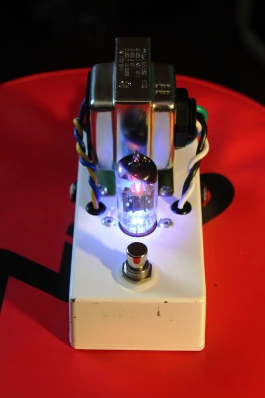
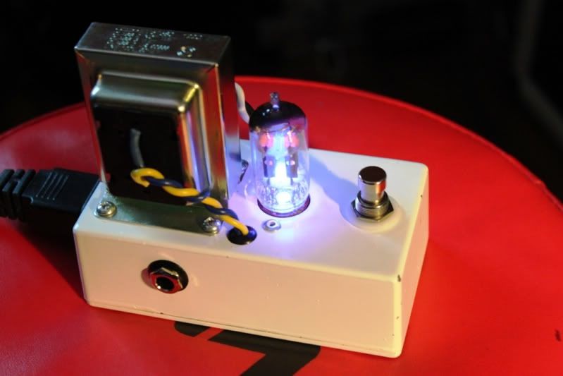
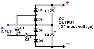
    Ive made a pedal using this circuit. Accept im using a 12ax7 and my B+ is 115 volts not 24v. It makes alot of noise and i realize now the resistors need to be of different values. i dont know how to calculate this stuff. Anyone know what i should change them to in order to make this pedal useful. thanks


  • #2
    This web page is your friend -

    AC Coupled Cathode Follower

    Also...why the 12AX7 over a 12AU7?
    Jon Wilder
    Wilder Amplification

    Originally posted by m-fine
    I don't know about you, but I find it a LOT easier to change a capacitor than to actually learn how to play well
    Originally posted by JoeM
    I doubt if any of my favorite players even own a soldering iron.

    Comment


    • #3
      Originally posted by Wilder Amplification View Post
      This web page is your friend -

      AC Coupled Cathode Follower

      Also...why the 12AX7 over a 12AU7?
      thanks for the link.

      ive got a couple 12ax7's laying around that all. this project was made from left overs so i want to see how it works out before i buy anything

      Comment


      • #4
        Originally posted by NFXP View Post
        thanks for the link.

        ive got a couple 12ax7's laying around that all. this project was made from left overs so i want to see how it works out before i buy anything
        At that plate voltage, going off of a load line I would replace R2 with an 820R resistor while replacing R3 with a 100K. However, you're only gonna have about 500mVRMS (1Vpk-pk) of input headroom due to the way the plate curves on a 12AX7 work in that config. Depending on how hot your guitar pickups are, you may overdrive the input of the circuit.

        If you were to replace those values with around a 7.5K/1M, you can double the input headroom but you won't have much current drive, which would defeat the purpose of the buffer in the first place.

        12AX7s, while they can work as a cathode follower buffer, are best suited as voltage amplifiers. 12AU7s are a much better valve to use as a current amplifier than a 12AX7 would be, which is basically what a cathode follower buffer is. It amplifies current so that you can drive lower loads without the load sucking the output voltage down.

        With a 12AU7 at the same voltage and a 800 ohm/22K combo, you'd have about 4Vpk-pk of input headroom (which is more than enough for most passive guitar pickups) and just over double the current drive than you'd have with a 12AX7.
        Jon Wilder
        Wilder Amplification

        Originally posted by m-fine
        I don't know about you, but I find it a LOT easier to change a capacitor than to actually learn how to play well
        Originally posted by JoeM
        I doubt if any of my favorite players even own a soldering iron.

        Comment


        • #5
          First, what kind of noise? Hiss, hum, buzz?

          Second, I think you'll need to include a schematic for the whole pedal, in particular the power supply. The power supply may be the main problem (depending on what kind of noise you're getting).

          Comment


          • #6
            The circuit should work fine with the values already shown, even with a 12AX7 at 115V. As d69err said, the noise problem lies elsewhere.

            Comment


            • #7
              Maybe the tube is oscillating due to the lack of a grid stopper resistor. Try a 10k in series with the grid, right at the socket pin.

              It looks great, but I'd be terrified of treading on the tube by accident.
              "Enzo, I see that you replied parasitic oscillations. Is that a hypothesis? Or is that your amazing metal band I should check out?"

              Comment


              • #8
                This is my power supply. i used 2.2uf for C1 and C2 and 10uf for C3 and C4
                Its running in paralell with the AC heater. I used the negative as a ground.


                then ive got a simple rectifier to power the led. accept i didnt ground it like this drawing says.


                maybe my problem is with gound loops. it make a loud buzzing sound. im affraid to hook up a guitar just yet. If i pull the tube the noise should go away if the problem is the tube circuit but not if its the power supply right.

                Comment


                • #9
                  Originally posted by NFXP View Post
                  This is my power supply. i used 2.2uf for C1 and C2 and 10uf for C3 and C4
                  Its running in paralell with the AC heater. I used the negative as a ground.


                  then ive got a simple rectifier to power the led. accept i didnt ground it like this drawing says.


                  maybe my problem is with gound loops. it make a loud buzzing sound. im affraid to hook up a guitar just yet. If i pull the tube the noise should go away if the problem is the tube circuit but not if its the power supply right.
                  It probably could be caused by ground loops coupled with the very high input impedance with the circuit.. I would :

                  1. Drop the 470K resistor down to 100K.
                  2. Ensure the input jack and output jack are isolated off the chassis..
                  3. Tie all ground connections to a common point inside the device.
                  4. As a side note, and I did this once, wired up the input jack backwards with the ground lug feeding the input, and the signal lug wired to ground... Not saying you did, but something to double-check..


                  -g
                  Last edited by mooreamps; 01-25-2011, 07:28 PM.
                  ______________________________________
                  Gary Moore
                  Moore Amplifiication
                  mooreamps@hotmail.com

                  Comment


                  • #10
                    Originally posted by mooreamps View Post
                    It probably could be caused by ground loops coupled with the very high input impedance with the circuit.. I would :

                    1. Drop the 470K resistor down to 100K.
                    2. Ensure the input jack and output jack are isolated off the chassis..
                    3. Tie all ground connections to a common point inside the device.
                    4. As a side note, and I did this once, wired up the input jack backwards with the ground lug feeding the input, and the signal lug wired to ground... Not saying you did, but something to double-check..
                    Thanks ill have to go over the whole thing with a fine tooth comb. I got rid of one ground loop and it helped alot. and ill have to double check my connections since its not passing guitar signal in bypass.

                    Comment


                    • #11
                      Ok ive dealt with the ground loop problems. Its dead silent now in bypass mode. the only time there is noise is when its on with power. Theres a deep buzz and crackling over top. its worse when i pull the tube.

                      Comment


                      • #12
                        Sorry for the cold shower, but why this tube buffer?
                        *Any* op amp buffer , or even a single Fet, Mosfet or even humbler bipolar will work better than this.
                        Certainly won't have buzzy crackling, etc.
                        Juan Manuel Fahey

                        Comment


                        • #13
                          Originally posted by NFXP View Post
                          ive got a couple 12ax7's laying around that all. this project was made from left overs so i want to see how it works out before i buy anything
                          Thought i was a good project to get started into the amp building world. plus its cooler.
                          no one drools over pictures of "*Any* op amp buffer , or even a single Fet, Mosfet or even humbler bipolar" buffers. If i really needed a buffer i would have bought one already.

                          Comment


                          • #14
                            What JM wanted to say, (rightfully IMHO), is that, of all the tube-based circuits, the buffer is possibly the one in which the peculiarities that make us all love tubes so much are not exploited at all. The buffer acts as an impedance adapter, its gain is (slightly less than) one, and its behavior is extremely linear, so it really makes no difference whether a buffer is based on a tube or not. The behavior is so similar that even some purists would accept the presence of a MOSFET buffer in an otherwise "all tube" amp, so, if we're talking about a tube buffer pedal, the "cons" clearly outweigh the "pros".

                            JM2CW

                            Best regards

                            Bob
                            Hoc unum scio: me nihil scire.

                            Comment


                            • #15
                              Yes, with a gain of 0.9 it's really gonna scream.
                              "Enzo, I see that you replied parasitic oscillations. Is that a hypothesis? Or is that your amazing metal band I should check out?"

                              Comment

                              Working...
                              X