 Tweet
Tweet
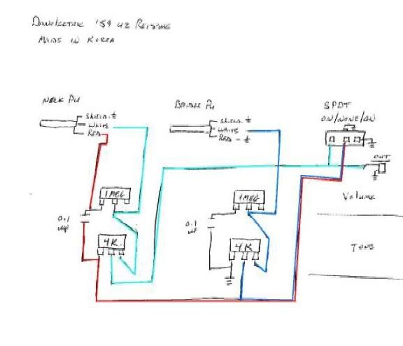
I received a Danolectric '59 U2 reissue ( made in Korea) that the customer tried to replace the PU selector switch (broken stem).
He bought a mighty Mite MM500. SPDT On/Both/On.
The middle position killed the signal.
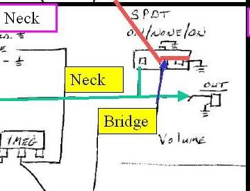
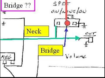
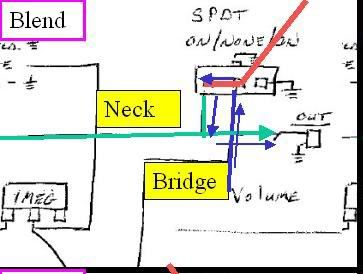
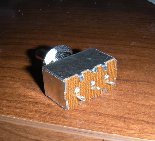
Upon inspection of the original switch, it appears to be On/None/On.
Does anyone know where to get this switch? SPDT On/None/On.
It appears that the switch is selecting On-Parallel/ None- Bridge/ On-Series.
Link to switch:3 position toggle switch mm500 Mighty Mite
He bought a mighty Mite MM500. SPDT On/Both/On.
The middle position killed the signal.
Upon inspection of the original switch, it appears to be On/None/On.
Does anyone know where to get this switch? SPDT On/None/On.
It appears that the switch is selecting On-Parallel/ None- Bridge/ On-Series.
Link to switch:3 position toggle switch mm500 Mighty Mite
Attached Files
Comment