Ad Widget

Collapse

Announcement

Collapse
No announcement yet.

Rickenbacker pickups

Collapse
X
 
  • Filter
  • Time
  • Show
Clear All
new posts

  • #31
    Sorry, I was off for a bit as I have a deadline to build a bunch of very high power transducers.

    For a living I used to listen to speakers, phono cartridges, microphones, etc and try to put numbers on sonic impressions. I needed very badly to be able to do that, because I designed them.

    We were all trained enough to hear and identify fairly simple resonances...a 6 db peak at 5K and a 4 db notch at 200 or something like that could be easily identified by ear.

    When things got more complicated we had to resort to descriptions like "hollow", "boxy" , "thick", etc.

    Our take at Shure was like this: The ear/brain is trained to use multiple complicated resonances (like comb filtering) to get spatial information. In a sense we use these much like bat or dolphin echo location. For example the resonant modes of a square box can give us an aural impression of a box! A blind person can tell the rough dimensions of a room just from the sounds heard. It's not time domain echo location but the frequency response effects of delays we process.

    Here's the thing... You recall that I am fortunate to have an Agilent impedance analyzer in the lab right now, and for grins I hooked it up to a guitar pickup in place. There are all sorts of things going on there....a real sqiggly line. In the impedance data I can easily see body resonance, shorted turn effects, and more.

    On top of that recall that the string motion consists of travelling waves along the string. As these waves pass through the pickup field area there will be powerful comb filter effects from the time delays involved.

    So yeah, complex resonances happen in pickups that could only be described by terms like quack, thick, edgy, etc. They are much less pronounced generally compared to the self resonance... which is the primary sound coloring phenomina.

    Will a driven coil tester energize all these effects? No, I don't think so. But it might give some useful information. I think my pickup SPICE model will be about as good.

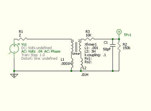
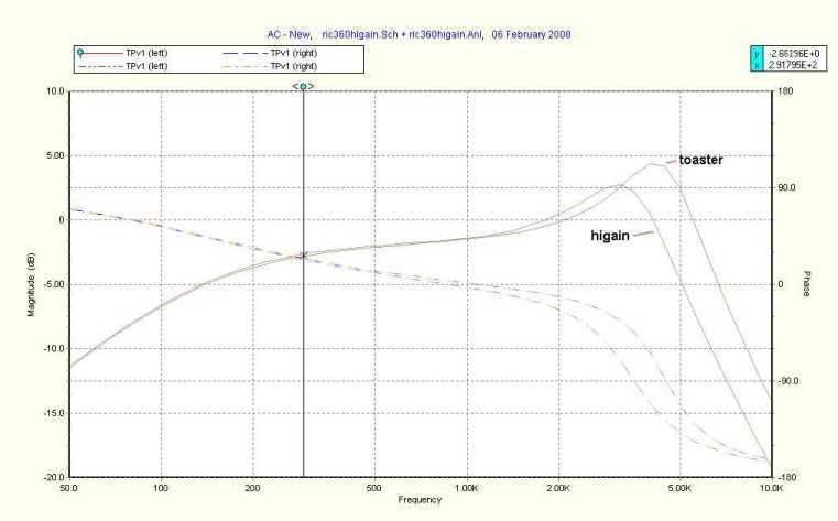
    Oh funny thing....I was messing with transformers connected to the ric 12 string. A step down certainly raises the self resonance, but the primary self inductance interacts with the series cap in the bridge pickup to create a big peak in the lower mids...about 180 hz. I saw it on the spice model, I heard it on my guitar... AND I heard it on the Byrds mr tambourine man!! So they used a transformer coupled direct in and I can hear it!!

    I came here to get pickup data just so I could get toaster sound from a higain. By putting in those resonances I think I have gotten very very close. Not exact, because the mag fields are not the same. But it's about 90% there. I think that's what analyzers, spice models, and testers can do. Some things they just aren't going to show though.
    Les Watts

    Comment


    • #32
      Their setup is a glorified audio impedance meter, nothing more.

      I'm magnetically driving a coil and I see clearly how the top
      half of the coil is doing most of the the signal generation and the
      bottom half is mostly inductive load. No impedance test will
      tell you that.

      -drh
      "Det var helt Texas" is written Nowegian meaning "that's totally Texas." When spoken, it means "that's crazy."

      Comment


      • #33
        Originally posted by Les View Post
        Here's the thing... You recall that I am fortunate to have an Agilent impedance analyzer in the lab right now, and for grins I hooked it up to a guitar pickup in place. There are all sorts of things going on there....a real squiggly line. In the impedance data I can easily see body resonance, shorted turn effects, and more.
        ....

        Will a driven coil tester energize all these effects? No, I don't think so. But it might give some useful information. I think my pickup SPICE model will be about as good.
        Which Agilent model are you using?

        In any event, two things occur to me:

        First, why would the driven-coil method see anything different than the impedance method? The same couplings between pickup and body resonances et al are present in either case.

        Second, it may be necessary to test pickups in situ but with body resonances suppressed, to distinguish pickup effects from guitar effects.

        Comment


        • #34
          Joe,

          I'm using the 4294A.

          http://www.home.agilent.com/agilent/...0&cc=US&lc=eng

          It is a very powerful instrument to say the least.

          I would never get to use such a thing for musical stuff ordinarily. My client is renting this for me to develop fourth order piezo transducers for an energy harvesting device. We actually create enough power from very loud sound fields to run electronics!

          As far as the driven coil thing....sure I think it would show the basic lumped parameter stuff just fine. But it's not what the string is doing. So I think the various comb filter/convolution effects will be different because the field will be different. I say try it and see...anyway I am not a pickup winder, but I agreed to assist in setting up a tester if people asked. The main thing is to run it from a transconductance (voltage controlled current source) amp. I have some circuits for that and will talk about it if anyone wants. First we need to get an idea of what a driver coil will put out.

          And yes the lumped parameter effects are best tested off the guitar. I just wanted to mention how much things like body resonance can effect the electrical impedance of a transducer. With the trancducers I am designing I can make them go from capacitive to inductive just by changing dimensions slightly on the cone radiator.
          Les Watts

          Comment


          • #35
            Originally posted by Possum View Post

            What I was hoping for and never found was something like an LCR meter that has a 10K test signal that would read AC resistance and inductance in that range but Joe says it all falls apart in testing pickups in those ranges.
            An impedance bridge like a General Radio or ESI do this very easily, I know the 250DA I use has external generator terminals, so I could hook up a signal gen there and use any frequency I want.

            Couldn't go to 10 kHz due to the capacitance of the winding, but as long as not too far above the resonant freq should get a measurement.

            Comment


            • #36
              Originally posted by Les View Post
              Joe,

              I'm using the 4294A.

              http://www.home.agilent.com/agilent/...0&cc=US&lc=eng

              It is a very powerful instrument to say the least.
              I'll say. And worth more than my car.

              I would never get to use such a thing for musical stuff ordinarily. My client is renting this for me to develop fourth order piezo transducers for an energy harvesting device. We actually create enough power from very loud sound fields to run electronics!
              I have some advice to offer. Stay away from the heavy metal folk: their sound fields will cause your harvester to explode.

              As far as the driven coil thing....sure I think it would show the basic lumped parameter stuff just fine. But it's not what the string is doing. So I think the various comb filter/convolution effects will be different because the field will be different.
              I'm not seeing this. The couplings between the various parts of the guitar, including the pickup, should be the same in either case. Inefficiency of one path compared to another could mask this, but aside from masking, how can they differ?

              I say try it and see...anyway I am not a pickup winder, but I agreed to assist in setting up a tester if people asked.
              Try it? For sure.

              The main thing is to run it from a transconductance (voltage controlled current source) amp. I have some circuits for that and will talk about it if anyone wants. First we need to get an idea of what a driver coil will put out.
              I'm not sure that one needs to do this, or that it will hurt. The main thing is to ensure that the driver coil is well damped and sufficiently wideband, so we measure the guitar et al and not the drive coil.

              And yes the lumped parameter effects are best tested off the guitar. I just wanted to mention how much things like body resonance can effect the electrical impedance of a transducer. With the transducers I am designing I can make them go from capacitive to inductive just by changing dimensions slightly on the cone radiator.
              I agree that the effect of body resonances can be large, but we need to distinguish the effects, so pickup makers can see what's going on. By the way, I was suggesting prevention of resonance, not necessarily removal of pickup from guitar. One way to do this is to clamp the guitar body to a plank with a piece of sorbothane between guitar body and plank.

              Comment


              • #37
                ....

                I made a drive coil like Lemme's, a humbucker bobbin with a 55 ohm coil. I think I used some fairly thick magnet wire, I don't remember now.

                I used a program called FuzzMeasure for Macs thats used to test speaker enclosures and microphones I think it is. It has a burst kind of thing which is a quick sweep of frequencies. I'm attaching a chart I did when testing a new thick blade pickup against a different version with thin blade and thinner magnet wire. I wanted to find out what the new pickup was doing versus the old one, and in this case it WAS useful. When you're ear testing different pickups its real easy to get ear fatigue and not know what the hell you're listening to, everything starts to sound the same. Anyway the black line is the first pickup, you can see its brighter. the new one is less bright which is what I wanted. The resonant peak is around 3K which is what most pickups are using this method. What I don't understand is how those physics guys are getting these charts with super sharp resonant peaks, every pickup I've ever measured has always had a very smooth peak, especially hand wound ones. Real cheap factory pickups have sharper peaks.
                Attached Files
                http://www.SDpickups.com
                Stephens Design Pickups

                Comment


                • #38
                  Possum,

                  That looks almost exactly like the curves I get from the SPICE model with a purely resistive load. No peak. Throw 500pf (guitar cord) across it and I get stuff like this:


                  Btw, this is using the shareware 5spice. It's free and super easy to use. I have some guitar scematic files if anyone wants them. The pickup is modeled by an inductance, series resistance, and shunt capacitance. I just right click on components on the schematic and try different values.This curve of course includes all the guitar circuitry and 750 pF cable capacitance across a 500k load.
                  Les Watts

                  Comment


                  • #39
                    Les, I sent you a PM about the schematics.

                    Possum, there will always be a peak due to the LC resonance, with or without additional guitar cord capacitance, and any real coil is going to have capacitance.

                    The peak can be flattened by resistance shunted across the coil (like for instance a volume pot).

                    It sounds like the input impedance (sound card input on the Mac?) of your setup is low enough that the peak is being flattened.
                    Last edited by Scott S.; 02-14-2008, 03:52 PM.

                    Comment


                    • #40
                      Does it make sense to characterize transducers by their conducted
                      impedance curves yet ignore their transducted energy curves?

                      Does it make sense to test a transducer according its sensitivity to
                      a local energy field such as time-varying sound pressure or magnetic flux?

                      Gedanken experiment:
                      If you constructed a guitar pickup, e.g.,
                      a single PAF coil of 65 layers at 65 winds/layer,
                      as a stack of 65 spiral winds instead of 65 layers,
                      would it make a difference?

                      If such a pickup were mounted in a strung and tuned guitar,
                      would the magnetic flux be the same through all spiral layers?

                      Would the winds at the top experience more flux than the bottom ones?

                      If the magnetic flux varies along the vertical axis of the coil...

                      -drh
                      "Det var helt Texas" is written Nowegian meaning "that's totally Texas." When spoken, it means "that's crazy."

                      Comment


                      • #41
                        Possum

                        I carefully looked at your response curves. I hear the statements about response curves usually being useless as far as determining the sound.
                        I did a quick model of what must have been your setup. I modeled it as a very loosely coupled transformer, which is what it is. I got just about exactly the curves you show. I have pictures but not the time to stick them somewhere.

                        You are right. The curve has almost nothing to do with the real response.

                        Let's look closely at the two lines. Mentally shift the lower one up to be over the upper one. If you do you will see that above 3kHz the curves are virtually Identical. That does not mean the wide versus narrow didn't do anything up high. It did, but the chart really doesn't show it, other than a level change.

                        What I do see is an LR hipass corner shift from about 500 Hz to 200 or so.

                        The big drop in LF response shown on the curves is not real. It's caused by driving the coil with a voltage sourse.

                        What we see is the higher permeability core pickup changing the DRIVER coil's inductance, and that is changing the false LF drop a good bit.

                        But certainly that increased the pickup inductance too. The curve does not show it though. I slapped an extra 0.5 henry on the pickup model and only got a 1 db change at 10k...almost inaudible. But I know the pickups would have a lot different sound.

                        Remember I'm not ragging anyone, just trying to help. I agree that this setup is mostly useless.

                        So let's fix it.

                        You guys don't have handy dandy Transconductance amplifiers laying around, so lets do an approximation. Let's increase the driver coil inductance. Let's take it up to a few hundred turns.

                        Now let's slap in a dummy load. Put a 250k or so volume pot resistor in. Put a tone circuit if you wish (small change). Then put in a real load like 1 meg with 750pf across it.

                        When you do that you will get a response like I showed before. Changes in inductance will show big time. The false drop in LF will be mostly gone, at least in the guitar's frequency range. With a transconductance amp and integrator it will be completely gone. I know my curves have a LF drop too...but that's real. It's the series cap in the Ric bridge pickup.

                        If you do these things I think you will find tester curves much much more representative of the sound and therefore more useful to you.

                        I can model it and show you pictures if you want me to.
                        Les Watts

                        Comment


                        • #42
                          This is cool!!

                          I've wondered why Possum's setup didn't work too well in the past, so maybe it can be fixed to show something more useful?

                          What is a transconductance amp Les? Is that an amp that is a bit of a current source? So maybe a cathode follower to drive these coils, or the solid state equivilants? It might be possible for me or people I know to whip something up if I know the requirements.

                          Thanks for your help Les.

                          Greg

                          Comment


                          • #43
                            Hey Greg.

                            A transconductance amp is a voltage contolled current source.

                            A regular audio amp is more like a voltage source, which has zero output impedance. Solid state amps are usually about 0.1 ohm, so pretty close.

                            An ideal current source has an output impedance of infinity. This can be approximated in an amplifier by putting a current sense resistor in a negative feedback loop.

                            A perfect current source will deliver the commanded current no matter what is hooked to it. If nothing was hooked to it the voltage would go to infinity.

                            I have prepared the circuits and graphs, and I hope Possum will be pleased with the results. Posting soon.

                            As far as my Ric toaster thing...i'm done. The only thing that is keeping me away from 1965 is the fact that I am using roundwound strings!
                            Les Watts

                            Comment


                            • #44
                              Ok, Possum and Saversan...here goes.

                              Here is the first circuit that duplicates the results Possum posted:


                              And here are the results with pickup inductance swept from 3H to 6 H with resistance swept square root of that:


                              Now here is the changed rig circuit:


                              And the results...same inductance/ resistance sweep.


                              Ok, a little discussion.
                              First, the circuit values might be a little different. But the poles are in the right place. That's what matters.

                              Now our ears tell us that if we double the inductance of a pickup the sound change is NOT going to be subtle. It will be a night and day thing. But look at the first graph at 3.5Khz. Only 1.5 db difference at the ear's most sensitive area. That is not a big change. It's also not what we hear.

                              Look at the second graph. 10 db change at 3.5kHz, and the better part of 10 thereafter. That's what my ears hear! It is the night and day thing that I would expect from going from 3 to 6 henries. Big Big change.

                              Also notice the false LF drop off is much less pronounced. Still some there, but not much. But if we look at the driven coile we see the inductance was increased a ton, but resistance only a little. So, we are talking fat wire...or a powdered iron core on the driver coil. At some point this will get such that it could perturb the pickup or just be too doggone big. We have to just do what we can and realize that the LF rolloff is false....or...use a current source ind integrator. Then there will be no rolloff, and prob a 1 turn driver coil will do the job if the amp can put out enough current.

                              One note....Notice I added inductance with extra inductors on the legs of the lossy transformer....this was done to normalize the curves and also because I cannot sweep a component value in a subcircuit in 5spice.

                              I hope this is helpful to you guys.
                              Les Watts

                              Comment


                              • #45
                                I don't think the drop in low frequency response is wrong, in fact its what I'm hearing. The first pickup uses a thin blade with 44 guage wire and it IS more boomy and less accurate in the low frequencies, this is typical of 44 guage wire. The second pickup has more accurate low frequency response and is more hi-fi sounding and you can see that in the curve. It uses 42 gauge wire and has much less self capacitance.

                                Is the blade affecting the driver coil, well sure probably but adding more winds to the driver is going to increase that effect even more.

                                Where all this gets sticky is when talking about which curve is more ACCURATE. Well that depends on what method of measurement you're using. All I care about is what the pickup itself is doing and not what it is doing in a guitar circuit, I want to see the raw data without other things being involved.

                                Greg I never said there was anything wrong with the method I used I said that its basically useless, you can get so tunnel visioned about making these charts that you forget that you're dealing with sound coming out of a guitar and amp and how PLEASING it sounds to the ears. Charts were only ever useful this one time to compare two pickups that nobody makes and are unique. I have the pickups to listen to and the chart as a visual of whats happening in a metal loaded coil. Whether its perfectly accurate or not doesn't matter because I only wanted to see a RELATIVE difference in what the two pickups are doing compared to eachother. It doesnt matter if they are perfect technically accurate representations of exact measurements of every tiny point on the chart, it only matters that I can see differences between the two using a method I am comfortable with and know what the results mean to me. Charts by themselves don't mean anything.

                                So bottom line really is if you want to mess with these techniques then you have to decide on a method you feel comfortable with and can afford to do and then learn how those charts relate to what your ears hear or to use when comparing two pickups against eachother. Pickup manufacturers don't even agree on what a proper method is, they all use different measuring techniques and none of them will tell you how they made the measurements. You have one manufacturer telling you that their strat pickups have reosnant peaks in the 10khz range and another with very simlar pickups tell you 3khz. Really worthless information to a buyer.

                                This all really reminds me of when Joe Gwinn started telling us dummies about LCR meters and how they could be useful to pickup makers. Back then I think I was probably the only guy who actually bought one and used the crap out of the thing to understand what those numbers mean. When you first get one the numbers are meaningless. But you get used to the method and keep results and THEN they mean something. Frequency response methods will only mean something after you use it in comparison to listening tests and the perfection of the method itself isn't all that important, what IS, is that you use the method consistently enough to know what your readouts mean to your work. But, back to square one, I just don't find much use for this stuff other than occasional amusement. Once you measure a bunch of different pickups and compare them to eachother then you're pretty much done with it. The only serious use of this technique is if you are making a pickup thats never existed before so have nothing to base anything on, and need to check minute differences between prototypes. Then it can be highly useful. Most members here though only make copies of stuff thats existed before, and with a simple LCR meter you can quickly see changes in metal loading, winding patterns, gauss level effects, and amount of wire on a coil. End of rant :-)
                                http://www.SDpickups.com
                                Stephens Design Pickups

                                Comment

                                Working...
                                X