Hello to everyone,
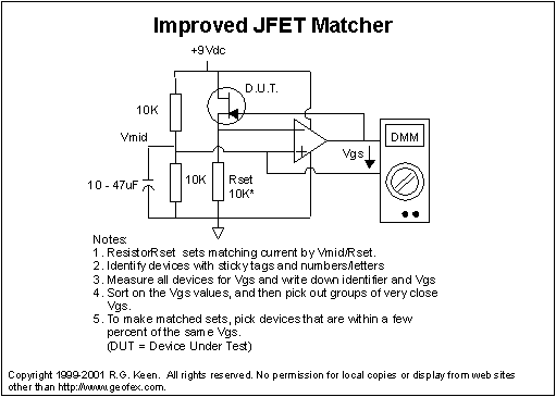
in order to build some phaser effects, I started to build a jfet-Matcher, but the da.... thing doesn't work and I can't find the error.
I attached my drawings to this post.
I copied this circuit:
Testing and Matching JFETS | Stompville
I didn't used a etched pcb, build on tagboard and wired the 3-position switch seperatly to the circuit.
For power supply, I used a print transformator ( 2x 9V with 0,75VA), followed by 2 rectifier circuit including voltage regulators, one circuit supplies the two digital meters ( Volt & Ampere, they light up), the other the jfet - circuit.
The connection from C to Pin 1 is soldered at the 3-position switch, the coloured dots in my drawing are the wires to the switch.
I twice checked all the soldering points,checked all the connections, tested the opamp, and used the multimeter to measure the voltage without plugged-in opamp/meters.
Everything looks fine, the only thing I'm not sure about is the voltage on (opamp-)pin 3: the multimeter only shows 0.98 volts.
Am I right, that resistor R1 and R2 are used as voltage divider ? So theoretically, it has to be 4,5 V ?
The original circuit also shows on the very right bottom a soldering point to ground - do I have to connect this ? (the enclosure is of plastic and the 230V power supply is without groundwire)
The last idea I have is that 0,75VA (AC) from the print transformator might not be enough to make the jfet-matcher work..
I'm thankfull for every tip or help
Best regards
Gokarna


 I liked to build this special jfet-Matcher also for the pleasure of building a nice device.
Comment