Ah, I see. I didn't realize your ground wasn't already wired up. Run the black wire from the power cord to one tab on the fuse (doesn't matter which tab). Then the other tab of the fuse to one of the black twisted wires from the PT. Then connect the other black twisted wire from the PT to the white wire from the power cord using a wire nut.
Doesn't matter. Neither the fuse nor the holder has an electronic polarity.
Yes. The mojo schematic is like the vintage schematic. But on the vintage amps, the ground wire from the OT was a bare wire that came from the coil and was soldered directly to the OT casing, which was then grounded to the chassis, and the output jack grounds to the chassis. With the mojo OT, you just connect the black wire directly to the jack ground.
on #1, where is the power switch? between the white chord and PT black wire, yes? it doesnt need to be connected in series with the fuse? thanks!
Doesn't matter. Neither the fuse nor the holder has an electronic polarity.
Actually for safety its better to run the mains active wire straight to the bottom tab of the fuse holder. If for some reason if you ever have the amp plugged in and the cap off the fuse holder, you don't want the ring terminal under the fuse holder's cap to be live.
How bout this?:
white ac chord wire goes to first black PT wire with wire nut. Black ac chord wire goes to lug on tip of fuse holder. jumper runs from other lug on fuse holder to switch, remaining black PT wire goes to remaing open power switch lug.
Is this correct and SAFE?
Green wire from ac chord is of course grounded to chassis under PT bolt.
thanks again for the help, i really appreciate it!
the wire colouring is different in this neck of the woods, so black and white doesn't mean that much to me. (Hey that's a good line for a song!)
Whichever is the active/phase wire goes to the bottom of the fuse holder, then from the top of the fuse holder to the main switch, then to the corresponding coloured wire on the PT (white-to white, black to black). Whichever wire is the neutral mains wire goes straight to the PT. Try googling up a mains wire colour page for your locality and see what it says.
(Edit - seeing as how you have two black wires coming out of the PT cover going nowhere in your pic, I take it that those are your primaries - doesn't matter which one you pick for which incoming wire.
Oh man....IT WORKS!
I am beside myself with joy right now.
It sounds awesome. It is nice and quiet too.
Thank you all so much for the help.
There is one issue so far.
This is hard for me to explain becuase I dont fully understand how the volume knobs interact, but I get some oscillation with both volume knobs on 12 and the middle pot (volume) will pop loudly when I turn to to 12 sometimes, depending on wether im plugged into the bright or normal channels. It almost sound like there is crud in the pot at teh twelve oclock spot on that pot, except its a real loud crackling popping kind of sound, not a scratchy pot sound.
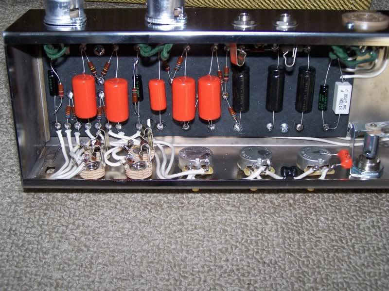
heres a shot of the pot wiring. is it possible for a ittle bit of solder cliping to fall into the gap in these pots and cause this crackling sound? It rally is lik a bad connection sound but only at 12 on the dial and only on this one pot.
The oscialltion i get on both normal and bright channels it seems and with or withou a guitar plugged in also.
Im stoked that it works and sounds so great for the most part tho! wahoo!
Actually for safety its better to run the mains active wire straight to the bottom tab of the fuse holder. If for some reason if you ever have the amp plugged in and the cap off the fuse holder, you don't want the ring terminal under the fuse holder's cap to be live.
The crackling pot disappeared after moving the amp across the room and tilting it a couple times to plug it back in. I think there may have been something in that pot, some debris maybe from my solder clippings...
The volume feedback thing...which ever channel im not plugged into , as long as i dont turn that volume knob up I am fine and can crank the amp to 12 .
Maybe this is how this amp works? it sounds like god's golden trumpet when cranked! I am in love.
The 5E3 is really fun indeed. There are some settings where it will howl at you depending upon volume, guitar, and note being hit (that can be a good thing or bad thing, depending). After you play with it a bit, you'll find your favorite sweet spots.
is it possible for a ittle bit of solder cliping to fall into the gap in these pots and cause this crackling sound?
Yes it is possible. You could try takin the pots apart and using desoldering braid (with a hot iron) to lift away any unwanted solder, but you're probably going to find it easier and more successful getting some fresh 1MA pots and putting them in (without getting solder inside them).
Building a better world (one tube amp at a time)
"I have never had to invoke a formula to fight oscillation in a guitar amp."- Enzo
After reading a bit and playing the amp some more...I now realize something is not quite as it should be. I can only use one volume knob at a time or i get this low pitched loud feedbacky sound like the speaker is being overloaded. Im not good at describing sounds so not sure if you could describe this as oscialltion. it seems to start as oscialltion and then grow quiclkly to that loud constant low pitched feedback.
I've never worked on an amp that has been powered up before. Never drained a cpacitor etc. But have ben reading and have prepared a little aligator clip, resistor and wire tool for draining the caps.
I have a hunch this may be a wiring issue. The two areas that come to mind are
1. I soldered the black or ground wire from my OT to the ground on the speaker jack. Maybe this should be soldered to the outside of the OT instead?
2. I didnt connect all the ground of my jacks together figuring they weregronded at the chassis. I didnt see any need to connect the 'switch' ion my shorting jacks to ground either, but maybe there is such a need?
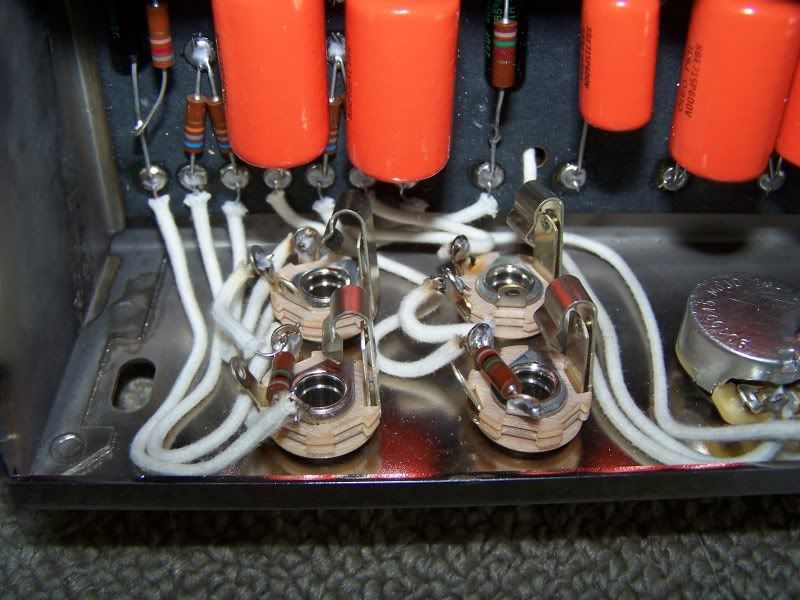
theres a shot of the jack wiring a couple posts back or i culd repost it if it would help.
Again to clairfy if possible. I get volume on both knobs...i can use either channel. Its juts whatever channel i m plugged into, I cannot turn up the volume knob for the other channel without getting this low pitched strong booming feedback/runaway oscillation.
even with only one voume knob, it sounds friggin fantastic, but obvioulsy i juST want it to work as it should nad have the full range of tonal possiblitiy its meant to have. Thanks in advance for the continued help. something tells me you cant just build one of these things and stop there.
Some fun, isn't it, Ben?
All I can tell you about the OT wiring and the input jacks, is I did it just the way you described on mine, and it works beauty, so I suspect the issue is elsewhere.
I put the black wire from the OT to the ground side of the output jack, and I didn't ground my input jacks, other than making sure they were cranked down tight. I did have to spend a good bit of time working on the grounding, as I had too many grounds, but yours does sound like an oscillation issue rather than grounding.
hmm..yeah, there is no buzz, hum or anythig else I wuld associate with a ground issue. My wiring is fairly short and i thought pretty neat and orderly.
take another look at this shot of the jacks.
On the first input jacks with the 1 meg resistors...do i need to connect the "switch" lugs to the ground lugs on these jacks? i see this done on other diagrams. for example here: http://www.el34world.com/charts/CommonHookups.htm
I agree with Reso Guy that it is not a grounding issue.
The switched terminals on the jacks should be explicitly wired, although I'm not sure that's the cause of your problem. Take care of that first, and then next stop if it continues: check the pot wiring.
Ben, the resistor should be attached to the hot lug of the jack at one end, then to both other lugs at the other end. Attached is a pic someone sent me to illustrate.
 Tweet
Tweet

Comment