New Month We are at $0 this month in Donations.Please consider making a donation. :)
Wishing everyone a Happy New Year and many repairs in the coming Months. Just remember it is YOU who helps this site be what it is. You are the reason people come here for no BS answers.
Happy NEW YEARS!!!!!!
Ben -- not sure what happened with your kit. I had green and white wire to spare when I was done. I did, however, "measure" it out carefully and tried not to waste any along the way, planning the wiring as I went. If you aren't careful to do that, you can waste it a way an inch or two at a time.
Nuts/screws and bolts: I had spare of those as well after I was done. I don't recall what size fit the tube sockets. I used two provided screw/bolt pairs to hold the eyelet board in. But I bought shorter ones since I didn't like how far they stuck out (I'm anal, I know). The self drilling screws work even without a pilot hole, I just didn't like that pointy tip stick out the back of the chassis waiting for me to poke/gouge my finger on it one day. Self tapping screws need to be predrilled, but they have a blunt end. However, they don't seem to be available any more.
I hope you get your parts sorted out! Mike at Mojo is a good guy and he'll help you out.
Yep, the guys at Mojo always helped me out, Sean in Customer Service especially.
I do agree it can be frustrating working on your own out there, but it will all come together at some point.
The insulator and the circuit board were predrilled w/ the two holes. It was so easy to zip 'em both to the chassis w two screws. Spacers would've been cooler for sure [or wiring the amp like a Hiwatt!] but it was all about saving time and money.
Whenever I get inside to fix an old one now the problem is so often rusty or otherwise bad connex under the tremelo bug. Sometimes just a new insulator slipped under there fixes it.
I laid my eyelet board and insulator board inside the chassis, lined them up where I wanted them, and drilled the two holes straight through both boards and chassis. After drilling the first hole I screwed that one down, then did the second to hold it steady.
Ive always felt a special connection to fender instruments and amps.
Building my first amp, one modeled after one of Leo's designs, what really appeals to me is the simplicity and logic of the design. The economy and functionality of the eyelet board mouting is a good example.
Well guys, the cloth wire came yesterday (thanks mojo!) and I got the board done and mounted and it looks great! or at least i think so!
I wired the tube sockets and did my heater wiring.
That leaves the jacks + preamp grounding.
The transformers. The switch and ac chord wiring, the pots, and the speaker jacks.
1. One thing i am still really confused on and dont know what to do abut is the .047 cap coming of the ground switch. A freind told me to ditch this cap (called it a deathcap, which i have heard is undesirable). If i do that, surely the wiring must be changed also?
2. Im looking for jack shots/photos to see how others do it. ditto speaker jck wiring. Im having the preamp ground and ground from 12ax7 pin 3, after it pases thru cap/resistor go the ground of input jack#1.
thanks again for the help, she's almost done! (I think?)
1. One thing i am still really confused on and dont know what to do abut is the .047 cap coming of the ground switch. A freind told me to ditch this cap (called it a deathcap, which i have heard is undesirable). If i do that, surely the wiring must be changed also?
After I got over being anal about keeping my amp true-to-vintage in favor of being safer, I changed my ground switch to a standby switch. Just bypass the switch for the power wiring and use it instead to switch the HV center tap to ground wire. That makes a perfectly good standby for the 5E3. Since the 5E3 doesn't really need a standby, there are probably other clever things you can do. I think some builders keep it there for vintage look but it does nothing.
2. Im looking for jack shots/photos to see how others do it. ditto speaker jck wiring. Im having the preamp ground and ground from 12ax7 pin 3, after it pases thru cap/resistor go the ground of input jack#1.
thanks again for the help, she's almost done! (I think?)
Hah! You think so? You'll have fun trying different mods once it's done. At least I have. I didn't think I would bother, but there are a few enhancers that are interesting.
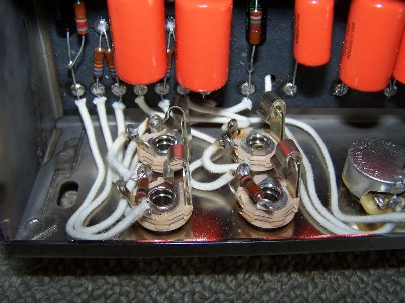
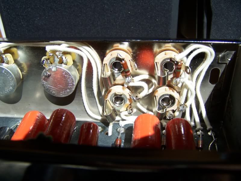
heres how i did the jacks.
I dont understand why some connect all the jacks grounds to each other with separate wires. arent they automatically grounded by touching the chassis? As you can see I didnt connect the grounds to each other, juts grounded the two boards preamp grounds to the ground on input #1 and let thatc ground itself to the chassis by contact only. is this wrong?
these are switchcraft "shorting jacks" if that makes any diff. mojo kit, again.
Okay, i want to ditch that deathcap, but didnt understand your explanation of the new wiring shceme mbratch. Im unfamiliar with terms like "hv center tap". my apologies. do I need a new switch or can i use the ground switch wired differently?
HV (or 'HT' for proper english-speaking countries ) centre tap is the Power Transformer's High-Voltage winding centre tap.
If you are taking out the death cap (which you should BTW), then yes take out any associated alternate-ground switch, and make sure the amp is wired with an up-to-date 3-wire mains system (including mains earth, which is permanently bolted to the chassis)
Building a better world (one tube amp at a time)
"I have never had to invoke a formula to fight oscillation in a guitar amp."- Enzo
Ben -- there are some long threads on grounding schemes for the 5E3, and lots of controversy over what's the "best". But there is consensus on one thing: if your scheme works, then it's good. So relying on the chassis for ground is OK for the jacks as long as it doesn't cause any ground loops and give you undesirable hum. Fender used a big brass plate behind the control panel.
For the ground switch, I agree with tubeswell. The simplest thing to do, as I mentioned, is just ignore it. Don't wire it up and have it do nothing. Just connect the hot, neutral straight through bypassing the switch. You could use the unused switch for something else, like standby, but it's not required for this amp. There are a couple of standby schemes. The ... erm.... HT center tap is red/yellow stripe wire connected to ground per the mojo diagram. One way to do standby is to connect it through the switch so that it is either grounded (on) or not (standby).
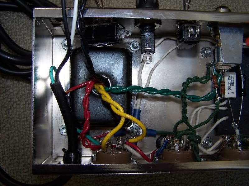
So ignore the ground switch. Then my white ac chord goes to one pole of the ppower switch, the other pole of the switch gets one of the black wires from the PT?
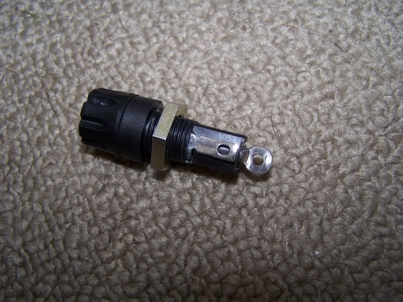
The other black wire from the PT will go to the fuse and the black wire from the ac chord will also go to the fuse. Is this correct? Does it matter which prong on the fuse gets which black wire? my fuse has one lug on its side and one on the tip.
Here is how i did my jacks. I understand that whatever works is the 'right" way. But having never built an amp before, the best I can do is look at what has worked for others. So when i see alot of others grounding their jacks, even tho i know them to be grounded already by contacting ther chassis...I wonder if "maybe THIS is the way that works?". also Im afraid of shocking myself somehow...thats probably not a legit concern with an ungrounded input jack...but since I know next to nothing ...I fear doing things in a manner other than how i see everyone else doing them.
anyway, I didnt ground the jacks figuring they are grounded to chassis already and adding another wire would just be making another ground loop.
whats puzzling for me is, I see lots of diagrams where they do chain all the jack grounds together. maybe they are using insulated jacks?
heres an artsy shot of the jacks(finally figured out how the close up function on my camera works...and gee Ive only had it for 4 years now)
hey guys, I cant thank you enough for the help and encouragement. I think i might be able to fire it up today if i can get these last couple questions taken care of.
Ben -- regarding the ground switch you could simply just disconnect (remove) the cap and be done. The ground switch will then just be a terminal post for the wires.
As far as grounding jacks, I've seen it both ways. Typically, though, when builders have grounded the jacks to the chassis, they've used the brass plate that the vintage amps used. Mojo doesn't provide those. So I chose a different scheme to ground the jacks. However, yours may still work fine. You just have to try it. There's no more risk of shock in that case than if you use a brass plate as long as you didn't wire power to the chassis.
I don't see the rest of your wiring, so hard to comment on what one might expect. Where are you tying your other ground points (e.g., the cathode cap/resistor grounds from the circuit)?
Nice pics, btw. And your wiring looks nice and neat.
on the ground switch, if its non functional, Id rather simply not connect it if at all possible. My thinking is that every connection and component, unless absolutely essiential, is just another chnace for degradation of signal...maybe thats not correct but i infer this from noticing that my favorite sounding amps are often the ones with the fewest components, knobs, switches, etc.
1. could I wire it up as proposed above without the ground switch? This is one part i REALLY wanna get right. I dont wanna flip that power switch and get zapped or zorch my components.
2. does it matter which lug of the fuse gets which black wire(either from PT or ac chord?)? again, my fuse has a flip up lug in the middle of the fuse holder and one big round lug on the tip
3. The black wire from the OT was not shown on the wiring diagram. I wired ti to ground of my speaker jack. is this correct?
Thanks again mbratch! and everyone else!
-Ben
edit for photos
fuse holder
remaining PT and ac chord wiring, switch on far left is unused ground.
1. could I wire it up as proposed above without the ground switch? This is one part i REALLY wanna get right. I dont wanna flip that power switch and get zapped or zorch my components.
Ah, I see. I didn't realize your ground wasn't already wired up. Run the black wire from the power cord to one tab on the fuse (doesn't matter which tab). Then the other tab of the fuse to one of the black twisted wires from the PT. Then connect the other black twisted wire from the PT to the white wire from the power cord using a wire nut.
2. does it matter which lug of the fuse gets which black wire(either from PT or ac chord?)? again, my fuse has a flip up lug in the middle of the fuse holder and one big round lug on the tip
Doesn't matter. Neither the fuse nor the holder has an electronic polarity.
3. The black wire from the OT was not shown on the wiring diagram. I wired tied to ground of my speaker jack. is this correct?
Yes. The mojo schematic is like the vintage schematic. But on the vintage amps, the ground wire from the OT was a bare wire that came from the coil and was soldered directly to the OT casing, which was then grounded to the chassis, and the output jack grounds to the chassis. With the mojo OT, you just connect the black wire directly to the jack ground.
Comment