Ad Widget

Collapse

Announcement

Collapse
No announcement yet.

Still no break-up. 2x 5F1's.

Collapse
X
 
  • Filter
  • Time
  • Show
Clear All
new posts

  • #61
    I'm wondering if that heater voltage is low enough to hinder the proper operation of the tubes.
    Definitely borderline, however the DC levels seem to indicate the tubes are functional.
    Originally posted by Enzo
    I have a sign in my shop that says, "Never think up reasons not to check something."


    Comment


    • #62
      Originally posted by eschertron View Post
      More gain! The cap keeps the cathode voltage from wiggling around under the force of the grid (signal) voltage. Theoretically, the output voltage can be double with, versus without the cathode bypass cap.
      More gain? not lots and lots and lots and lots -less- gain... so it will only distort at vol 9.5? godammit.

      As to the 'cathode bypass cap' off pin 8 of V2: it reads 470r ok switched off (& 22.5v on as per ^ figures) but I think isn't it a 1w? its like all the others anyway (bar the tiddly 1/4w I think 1.5 over on the far RHS). I forget what size resistors are these majority lot as its been a while since I poked and prodded an amp.

      Comment


      • #63
        Originally posted by g-one View Post
        I'm wondering if that heater voltage is low enough to hinder the proper operation of the tubes.
        Definitely borderline, however the DC levels seem to indicate the tubes are functional.
        *SORRY VAC reading error* ..I measured VAC across the rectifier not the flamin V2.

        Figures ammended (V2 heaters are VAC 6.3v).

        I will await JazzP's perusings. Thanks chaps, Sea Chief.
        Last edited by Sea Chief; 10-02-2014, 07:18 PM.

        Comment


        • #64
          Originally posted by Sea Chief View Post
          Figures:
          V2: Pin 3 & 8 (392v, 22.5v)
          Does this seem a little hot even for a Fender amp? My calculation results in over 17W dissipation.

          Even so, the DC readings look about right for this amp to me. If the signal's not getting lost somewhere, it should be every bit as loud as you'd expect. I'm wondering about the screen voltage on V2 (pin 4?).

          My last build was plagued by bad solder joints. Not that I could see it, but by troubleshooting and reheating the spots where the signal didn't get through, I brought the amp to life. A simple fix and quick, once I got a clue about what was actually happening. Not saying that's the problem here, but a familiar 'guru' on this forum would always begin his advice with "resolder the board". In the absence of a detailed diagnostic, sometimes that's the only thing a tech can do.
          If it still won't get loud enough, it's probably broken. - Steve Conner
          If the thing works, stop fixing it. - Enzo
          We need more chaos in music, in art... I'm here to make it. - Justin Thomas
          MANY things in human experience can be easily differentiated, yet *impossible* to express as a measurement. - Juan Fahey

          Comment


          • #65
            I'm going to also re-appraise it being only 2w as when I tried it thru my 112 (bog standard 12" 8Ohm) it was significantly louder, on a par with amp1 I'd say. Its plenty loud enough, they both are.

            The OT is defo rated as 2w on its spiel- what this number is then I'm at a loss/ if its a ballpark figure its sure a damn big ballpark then. As you can see its a diddy little unit..

            Comment


            • #66
              The B+ seems a bit high for a SE 6V6 amp. 340v is what's listed on my schematic for the 5F1. And you would have to adjust that 470r to maybe 330r/2W to get the same bias.

              Also, V2 Pin #4 may need to be measured for full disclosure.
              Now Trending: China has found a way to turn stupidity into money!

              Comment


              • #67
                V2 Pin 4= 374v.

                I do notice the 6v6 gets pretty hot.

                (the fender schematic shows 295v at V2 pin 4 does it not?).

                Comment


                • #68
                  Originally posted by Sea Chief View Post
                  V2 Pin 4= 374v.

                  I do notice the 6v6 gets pretty hot.

                  (the fender schematic shows 295v at V2 pin 4 does it not?).
                  If you have a 6L6 laying around, you might try putting it into the power tube spot. It should be quite happy with the higher B+ voltage.
                  If it still won't get loud enough, it's probably broken. - Steve Conner
                  If the thing works, stop fixing it. - Enzo
                  We need more chaos in music, in art... I'm here to make it. - Justin Thomas
                  MANY things in human experience can be easily differentiated, yet *impossible* to express as a measurement. - Juan Fahey

                  Comment


                  • #69
                    Originally posted by Sea Chief View Post
                    I'm going to also re-appraise it being only 2w as when I tried it thru my 112 (bog standard 12" 8Ohm) it was significantly louder, on a par with amp1 I'd say. Its plenty loud enough, they both are.

                    The OT is defo rated as 2w on its spiel- what this number is then I'm at a loss/ if its a ballpark figure its sure a damn big ballpark then. As you can see its a diddy little unit..
                    Louder with a 12, no wonder. You get low mids and lows the 8" doesn't deliver, just turns to heat. And if you found the specs, probably you'll see more efficiency overall with the 12. No need to snoop out all the numbers though, your ears are telling you what's going on. The 5W OT offered probably looks the same, weighs a tiny bit more. Wire inside likely a little thicker.

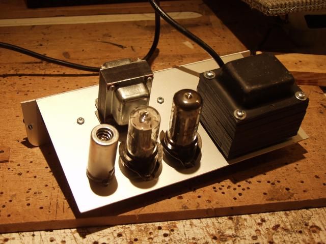
                    Nice workbench photo. Amp looks good, and I think we all have a "drill board" or 2, perforated with a thousand random holes.
                    This isn't the future I signed up for.

                    Comment


                    • #70
                      Anyone else notice that the input load resistor is 68k!?! WTF Replacing that with a proper 1M resistor might help!!!

                      And I'll second LT's post. Replace that under rated cathode resistor before raising the gain or it'll be blown to smithereens.

                      EDIT: On second look it may be that the 68k I mentioned is another input resistor, but I'd check the input wiring anyway in case there's an error. It's hard to see in the dark photo's. Just plug into the "high" input and measure the ohms from the jack tip to chassis. It should be 1M.
                      Last edited by Chuck H; 10-03-2014, 03:55 AM.
                      "Take two placebos, works twice as well." Enzo

                      "Now get off my lawn with your silicooties and boom-chucka speakers and computers masquerading as amplifiers" Justin Thomas

                      "If you're not interested in opinions and the experience of others, why even start a thread?
                      You can't just expect consent." Helmholtz

                      Comment


                      • #71
                        Originally posted by Chuck H View Post
                        Anyone else notice that the input load resistor is 68k!?! WTF Replacing that with a proper 1M resistor might help!!!

                        And I'll second LT's post. Replace that under rated cathode resistor before raising the gain or it'll be blown to smithereens.

                        EDIT: On second look it may be that the 68k I mentioned is another input resistor, but I'd check the input wiring anyway in case there's an error. It's hard to see in the dark photo's. Just plug into the "high" input and measure the ohms from the jack tip to chassis. It should be 1M.
                        I haven't been able to make out anything on the 'gubbins' photo, but have had a thought for some days, "did he swap the 68K and 1M?" That would hobble the signal something awful, right at the input
                        This isn't the future I signed up for.

                        Comment


                        • #72
                          Just a thought.

                          Turn it off. Turn the volume all the way up. measure resistance from the pot WIPER to ground. Does it read low or does it read about the value of the 1meg pot? Checking the shielded cable did not melt through the inner insulation during solderwork.


                          I can't see the OT connections other than a small unexpectedly white wire to pin 3 of the power tube, and what COULD be a red wire at the speaker jack. So: what is the resistance from pin 3 of that tube to the B+ in the lower left corner?

                          And can you link us to the exact transformer you are using?


                          In the interest of being systematic:
                          Apply a signal to the input, do not change this signal once set. Have the volume all the way up on the amp. use a dummy load if you don't want to listen to this noise. Now measure signal level at the input jack, at the grid and at the plate of all three stages.
                          Education is what you're left with after you have forgotten what you have learned.

                          Comment


                          • #73
                            Hi Enzo- Im not sure why Chuck H saw a 68k input resisitor, its defo a 1M (bith jacks wired ok/ correct diminished vol level between them afaict).

                            Turned off, vol middle lug to gnd = 920 Ohms.

                            Turned off still, V2 pin 3 to btm LH corner point on board = 800 ohms.

                            [White wire indeed at V2 pin 3 from OT primary side, red wire at spkr jack is the 4ohm OT secondary side. OT specs found in section 3/4 way down page. 1st eg/ has similar colour wires & 35x35cm base: Transformers ].

                            Can you remind me how to use a dummy load? (a fat 4 Ohm resistor wired to a mono jack plug or s'thing?).

                            Most helpful chaps- thanks, your Chief.

                            Comment


                            • #74
                              Well there you go. Your 1 meg pot measures 920 ohms. So find out about that.


                              What do you measure for resistance between the end lugs on the volume pot, turned all the way down. If we get 900 ohms still, then the pot seems to have issues. but if the pot itself measures the 1 meg, but turning the volume up drops it to 900 ohms, then I suspect the shielded cable.
                              Education is what you're left with after you have forgotten what you have learned.

                              Comment


                              • #75
                                Originally posted by Enzo View Post
                                Well there you go. Your 1 meg pot measures 920 ohms. So find out about that.


                                What do you measure for resistance between the end lugs on the volume pot, turned all the way down. If we get 900 ohms still, then the pot seems to have issues. but if the pot itself measures the 1 meg, but turning the volume up drops it to 900 ohms, then I suspect the shielded cable.
                                I measure 920 K still turned to 0 or 12. Its a cts/ relatively new too, wouldn't it be surprising if it had issues?

                                I changed the 470r cathode bypass cap's resistor to one 2x the size- I think min its a 1w/ poss 2w. I also changed the input capacitor to a 25/25 Ruby I had from an old board, its double the size & seemd to make the tone slightly better (I think).. but with caveat of some slight buzz/ very slight popping once fingers touch strings.

                                Comment

                                gebze escort kurtköy escort maltepe escort
                                pendik escort
                                betticket istanbulbahis zbahis
                                deneme bonusu veren siteler deneme bonusu veren siteler
                                slot siteleri
                                mobile casino no deposit bonus
                                deneme bonusu veren siteler bonus veren
                                streameast
                                bonus veren siteler
                                deneme bonusu veren siteler
                                deneme bonusu veren siteler deneme bonusu veren siteler
                                bahis siteleri
                                deneme bonusu deneme bonusu veren siteler Canlı casino siteleri
                                Working...