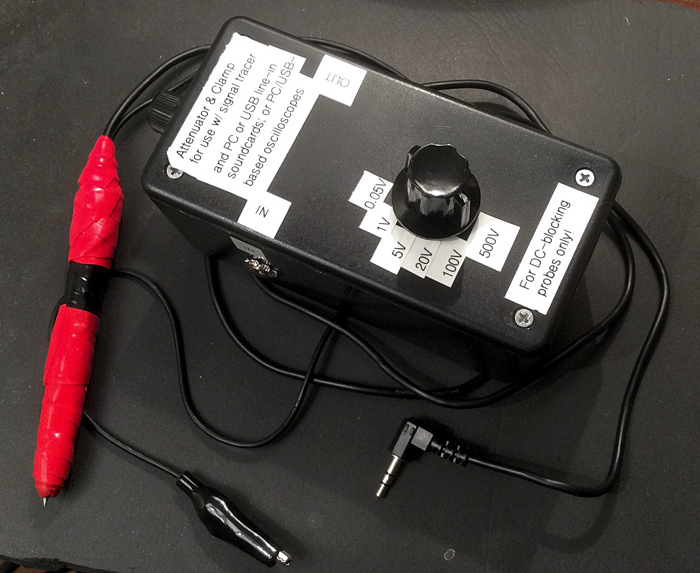
So having lots of awake time at 3 a.m. these days, I did up a new signal tracer with 0.022uF blocking cap, and a JMF-style attenuator plus clamp to go with it. I also mocked up the attenuator in iCircuit to see how it works. The mock-up suggests that for each suggested voltage range, the attenuator will keep max AC voltage at that range to a bit under a quarter of a volt. This is well under the voltage level at which the clamp would come into play.
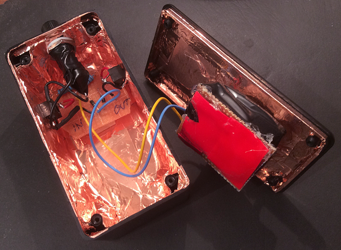
Below are photos - yes, rude work, but plenty good for my purposes. The attenuator switch is pretty heavy duty (I forget the power rating). I mistakenly (this is 3 a.m., remember) included the fuseholder with 0.5A fuse before remembering the fuse had only been for if I didn't use an attenuator, just the diode clamp. Maybe the fuse will be helpful for when I re-animate the Frankenstein monster. Also note the screws in the lid are not live to the circuit in any way - perhaps it doesn't matter but I don't like surprises.
The new tracer is built around the shell of a free bank pen. It's so fat because first of all the pen shell is fat, and then there's the copper shielding plus two types of tape for insulation & good grip. The 1/8" plug on the tracer is nominally stereo but ring is not connected. The attenuator out shorts ring and tip so they both get the hot mono signal; but this needs to be checked to see if OK with any sound card used.
Anyway, a fun new tool. Now I can use it to chase down the latest noise in my little PCB amp - static during power up/down, tube-pulling suggests it's near the PI; maybe from some SM component crapping out, or from the PCB flexing one too many times during all the sessions I worked on it? Ah the joy.


Comment