Announcement

Collapse
No announcement yet.

Test bench amp setup advice

Collapse
X
 
  • Filter
  • Time
  • Show
Clear All
new posts

  • #16
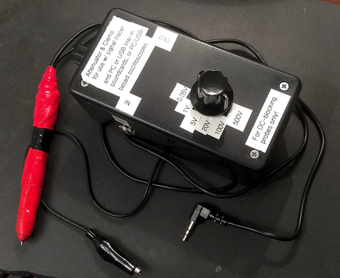
    So having lots of awake time at 3 a.m. these days, I did up a new signal tracer with 0.022uF blocking cap, and a JMF-style attenuator plus clamp to go with it. I also mocked up the attenuator in iCircuit to see how it works. The mock-up suggests that for each suggested voltage range, the attenuator will keep max AC voltage at that range to a bit under a quarter of a volt. This is well under the voltage level at which the clamp would come into play.

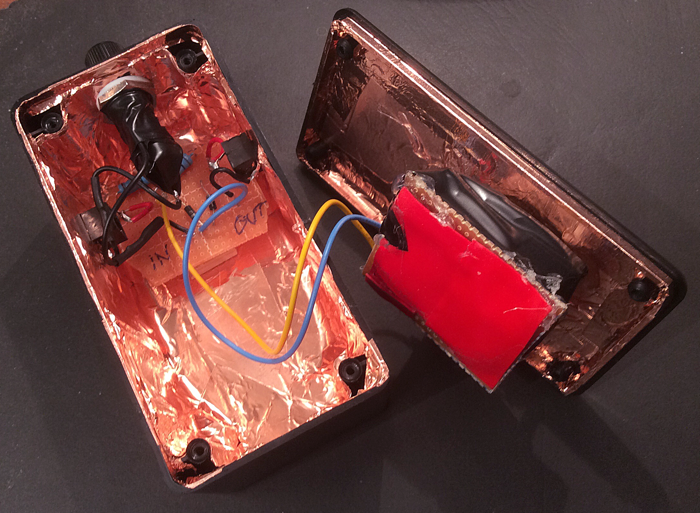
    Below are photos - yes, rude work, but plenty good for my purposes. The attenuator switch is pretty heavy duty (I forget the power rating). I mistakenly (this is 3 a.m., remember) included the fuseholder with 0.5A fuse before remembering the fuse had only been for if I didn't use an attenuator, just the diode clamp. Maybe the fuse will be helpful for when I re-animate the Frankenstein monster. Also note the screws in the lid are not live to the circuit in any way - perhaps it doesn't matter but I don't like surprises.

    The new tracer is built around the shell of a free bank pen. It's so fat because first of all the pen shell is fat, and then there's the copper shielding plus two types of tape for insulation & good grip. The 1/8" plug on the tracer is nominally stereo but ring is not connected. The attenuator out shorts ring and tip so they both get the hot mono signal; but this needs to be checked to see if OK with any sound card used.

    Anyway, a fun new tool. Now I can use it to chase down the latest noise in my little PCB amp - static during power up/down, tube-pulling suggests it's near the PI; maybe from some SM component crapping out, or from the PCB flexing one too many times during all the sessions I worked on it? Ah the joy.


    Last edited by Usable Thought; 01-27-2016, 11:35 AM.

    Comment


    • #17
      Cool

      The mock-up suggests that for each suggested voltage range, the attenuator will keep max AC voltage at that range to a bit under a quarter of a volt. This is well under the voltage level at which the clamp would come into play.
      That's the idea behind it
      Juan Manuel Fahey

      Comment


      • #18
        Thanks for all the replies.
        I have decided to use a different power amp for my signal tracer instead of the AV receiver.
        It is a basic amp with a volume control and can deliver 50W @8ohms load.
        This brings me to my next question:
        How does one practically determine the amount of series diodes needed for the clamping?
        Obviously the "sensitivity" of the amplifier changes as the volume pot position is changed.

        Comment


        • #19
          A 50 watt signal tracer? Wow.

          I find that the little very cheap basic amplifiers with 6" speakers that they throw into starter packs for beginner guitarists make easy and convenient tracers. Put the series cap inside the amp, and then your probe ware can be anything shielded, even a scope probe.
          Education is what you're left with after you have forgotten what you have learned.

          Comment


          • #20
            Originally posted by Enzo View Post
            A 50 watt signal tracer? Wow.

            I find that the little very cheap basic amplifiers with 6" speakers that they throw into starter packs for beginner guitarists make easy and convenient tracers. Put the series cap inside the amp, and then your probe ware can be anything shielded, even a scope probe.
            Well, i have the amp on my bench for testing preamps, speakers etc. might as well use it for signal tracing too.

            Comment


            • #21
              You don't want to overload your amp input and with most amps the input sensitivity wouldn't change with volume because very few amps have the volume control before the first gain stage, and it's that you need to protect. The clamping voltage depends on the forward voltage drop of the diodes. So, with a single pair you can go down to 0.1V with Schottkys, 0.2V Ge and around 0.6V Si.

              What you need depends on the input sensitivity of your amp, but under most conditions I can think of you wouldn't need anything other than a pair of Si diodes to protect the input. If that results in clipping try the other types, or a lower sensitivity input.

              Comment


              • #22
                The idea is not perforating the first transistor base to emitter (or gate-source) junction, on the other side not clipping a signal which was perfectly clean, so clamping usually must *not* happen under normal conditions.

                I am very paranoid about notebook microphone inputs because I don't have the schematics, can't repair parts that are mounted in a Motherboard , even if I knew/could it would probably use some house number unobtainable SMT IC , the "sound card" is not plug in replaceable and killing it might make my notebook practically unusable, so paranoia is justified.
                Under that mountain of disadvantages I try to not send more than 100mV to 200mV (tops) there and clamp with a pair Si diodes which means 650/700mV peak.

                If you are using a cheap guitar amp and want to still be able to plug a normal guitar there, a couple parallel back to back red Leds is fine: 1.9V peak, no normal guitar will clip them, yet such signal level will kill no B-E junction I know.

                Many Op Amp based preamps (notably Peavey and Crate) use a couple diodes connected to +/-15V rails, meaning they will clamp only > 15V peak signals; they can get away with that because most modern Op Amps have that range of common mode signal capability.

                Some add a couple antiparallel Si diodes from +In to -In because a few Op Amps are more sensitive to that than to signal voltage to ground.

                Tube preamps of course do not have that problem, they can easily stand 100V RMS at the grids (happens all the time in overdriven Guitar amps).
                Juan Manuel Fahey

                Comment

                Working...
                X