If this were a thread about very high powered ultralinear outputs I'd say the phase inverter should be part of the discussion. It's not uncommon to need well over 100 volts grid to grid to drive a high powered ultralinear output section.
On the other hand- one of the benefits of having screen voltage at a substantially lower voltage than the plates is the reduced negative grid bias- which in turn means less drive before you run into AB2 operation. Look at the datasheet for almost any output tube- 43% ultralinear takes around twice the grid drive. Even a basic split load inverter running on a 300 volt supply should be able to drive a big tube tube to clipping if it's running the screens at substantially lower voltage. Of course adding mosfets or cathode followers and driving the output into AB2 will give you even more output!
And that's exactly why the question regarding the PI...the fact that tubes in dual rail operation with the screens at 1/2 the plate don't need near the grid drive that a regular sliding screen amp or a UL amp needs.
I know I can drop the PI gain by lowering the plate resistors, but was just curious to know if one of the other PI circuit types was better suited to these operating conditions.
Jon Wilder
Wilder Amplification
Originally posted by m-fine
I don't know about you, but I find it a LOT easier to change a capacitor than to actually learn how to play well
Originally posted by JoeM
I doubt if any of my favorite players even own a soldering iron.
It depends on how you want it to sound- if you're going for traditional high-powered guitar sounds you're left with a few different basic designs. I'd say you've got split load (Ampeg b15n, Sunn200s, etc), split load plus driver (SVT, Marshall Major), FMV LTPI (bassman, plexi, BF twin reverb), and the Hiwatt fixed bias PI. There are others but when I think of high powered amps that enjoy a good tonal rep it's usually one of the above designs or some variation on them.
I think it's up to you- which do you prefer?
It says something that so many amps have blindly copied standard Marshall and Fender phase inverters. They can be made to produce a lot of output voltage into reasonable loads and can be re-designed to use a lower Ra tube (for driving more tubes/grid leak resistors) and still distort in the way that is so well-loved.
I still like split load for some designs though- you can run a lowish Ra triode well over its published voltage if you keep the current down and get a lot of grid drive.
jamie
Last edited by imaradiostar; 04-09-2010, 02:32 AM.
Reason: added something that I forgot to type.
It depends on how you want it to sound- if you're going for traditional high-powered guitar sounds you're left with a few different basic designs. I'd say you've got split load (Ampeg b15n, Sunn200s, etc), split load plus driver (SVT, Marshall Major), FMV LTPI (bassman, plexi, BF twin reverb), and the Hiwatt fixed bias PI. There are others but when I think of high powered amps that enjoy a good tonal rep it's usually one of the above designs or some variation on them.
I think it's up to you- which do you prefer?
It says something that so many amps have blindly copied standard Marshall and Fender phase inverters. They can be made to produce a lot of output voltage into reasonable loads and can be re-designed to use a lower Ra tube (for driving more tubes/grid leak resistors) and still distort in the way that is so well-loved.
I still like split load for some designs though- you can run a lowish Ra triode well over its published voltage if you keep the current down and get a lot of grid drive.
jamie
Duh...I don't know why I didn't think about possibly running a tube with a lower gain factor if the LTPI circuit I used had too much gain to begin with. You can go either way really...change the gain of the circuit design or use a lower gain tube..that's IF the grid drive provided by the PI circuit is too much.
I just put in the order for my screen tranny and the output tranny. I think through the R&D phase I'm gonna have a second plate tranny made with dual 225VAC HT windings (I should've had them do that on this one that I just received but didn't think to) and try the supply config where one winding is the screen supply while the other one is a 2nd 1/2 voltage supply that gets floated on top of the screen supply. In all honesty, I don't think there's much of a difference between doing that and using the center tap/half voltage node of a FWB doubler as your screen node...at least on the schematic there doesn't appear to be that there'd be much of a difference.
Jon Wilder
Wilder Amplification
Originally posted by m-fine
I don't know about you, but I find it a LOT easier to change a capacitor than to actually learn how to play well
Originally posted by JoeM
I doubt if any of my favorite players even own a soldering iron.
Originally posted by Wilder AmplificationView Post
Duh...I don't know why I didn't think about possibly running a tube with a lower gain factor if the LTPI circuit I used had too much gain to begin with. You can go either way really...change the gain of the circuit design or use a lower gain tube..that's IF the grid drive provided by the PI circuit is too much.
I just put in the order for my screen tranny and the output tranny. I think through the R&D phase I'm gonna have a second plate tranny made with dual 225VAC HT windings (I should've had them do that on this one that I just received but didn't think to) and try the supply config where one winding is the screen supply while the other one is a 2nd 1/2 voltage supply that gets floated on top of the screen supply. In all honesty, I don't think there's much of a difference between doing that and using the center tap/half voltage node of a FWB doubler as your screen node...at least on the schematic there doesn't appear to be that there'd be much of a difference.
Again Let me reiterate what I said above, and that many have stated since then:
The whole point of the design process is for you to make that decision, and put in the bench time ironing it out... figuring out what works best for the circuit in it's entirety, Especially since this is an amp you have quite openly stated you want to COMMERCIALIZE AND SELL TO PEOPLE.
Plus you have already received affirmation here from people that have utilized this topolgy before with the results you hoped for, what else are you looking for?
you can make the decision based on the purpose, and then change it. For example If you are going for that "Textbook Perfect" jive (in so much as there is such a thing), and are not comfortable, or have no desire to use active circuitry to help things along, go for a cathodyne.... it's not set in stone, and you can always change it.
Here's a new question for you what kind of affirmation are you looking for?
Just F@ck'n Do It! (Phil Knight)
It depends on how you want it to sound- if you're going for traditional high-powered guitar sounds you're left with a few different basic designs. I'd say you've got split load (Ampeg b15n, Sunn200s, etc),
jamie
To paraphrase Frank Zappa... Shut up and wield yer soldering iron!
Or as Bob Moog was told by his mentor Raymond Scott:
"Your problem is, you believe that when you think about something, it's done."
A lot of smart people fall into the trap of sitting and endlessly debating stuff on forums, when they could get the answer for themselves in 5 minutes. I've seen whole careers wasted this way. (No, not mine! There's still time left to turn it around!)
To reiterate what we've said: There's nothing magical about the dual rail thing, just think of it as an ordinary amp with the plate voltage boosted up. The drive requirements to the power tubes are no different, and you can use any PI arrangement that would work with those tubes in an ordinary amp. The LTPI is a safe bet. (I forgot to mention that I used a 12AT7 in mine. A 12AX7 worked too, but I always preferred the sound with a 12AT7 in both PI configurations.)
In relation to the "sliding screen" thing: You can show that an unbypassed screen resistor reduces the gm of the tube. So if you decrease the screen voltage, then you have to make the screen resistor smaller to maintain the same power output, and that increases the gm, so less drive is needed.
"Enzo, I see that you replied parasitic oscillations. Is that a hypothesis? Or is that your amazing metal band I should check out?"
Plus you have already received affirmation here from people that have utilized this topolgy before with the results you hoped for, what else are you looking for?
It's a deep hole to fall into when you spend more time working the paper, instead of working the build. Either scheme would probably work just fine ; except for a stereo build for home audio, in which case ; myself ; I set-up the dual rail of equal high voltage for each channel ; instead of the split voltage rail as I mentioned earlier.
-g
______________________________________
Gary Moore
Moore Amplifiication mooreamps@hotmail.com
Well everything is in process of. I've got the plate tranny and I'm waiting on the output and screen tranny.
I just have a tendency to overthink shit really. But the whole point of the post was to get others' experiences with dual rail amps as I've never built one (all the amps I've built were the standard Fender/Marshall power amps). But yes Steve you're right...it's just an amp of a higher plate voltage.
Jon Wilder
Wilder Amplification
Originally posted by m-fine
I don't know about you, but I find it a LOT easier to change a capacitor than to actually learn how to play well
Originally posted by JoeM
I doubt if any of my favorite players even own a soldering iron.
not sure why you would need the extra power transformer for the screens. I did both split rails and twin rails with only one.
-g
probably so he doesnt have to get one custom wound with 2 secondaries with the voltages he wants. this way he can choose 2 tranies with voltages that suit.
probably so he doesnt have to get one custom wound with 2 secondaries with the voltages he wants. this way he can choose 2 tranies with voltages that suit.
Actually I've seen it done wtih a center tapped winding and a doubler circuit. But honestly there are quite a few ways to do the dual rail arrangement.
The whole idea behind two trannys was to isolate the screens from the plate supply so that the screens were not at the mercy of the plate supply. Put the plate and heaters on one tranny and the screens and bias on the other. But for the sake of simplicity I'd like to try two HT secondaries independently bridge rectified and float one on top of the other as well as the FWB doubler circuit and see if one affects the other.
The only thing though is that I can't really see much of a difference between the floating and the FWB doubler arrangements. Either way the screens are pulling from one cap while the plates are pulling from both while the caps are getting charged to 1/2 the total plate supply voltage. The only difference I see is that the FWB doubler resembles a grounded center tap rectifier whereas the floated arrangement FWB rectifies both windings.
The other thing too is that the only way I can see to fuse both supplies with 1 fuse would be to fuse the ground feed from the negative side of the supply. I know that's not "standard practice" but it's the only way I can see to have a fuse that's common to both supplies.
You're right. I meant B18N which is ac coupled split load.
I think a fine example of the dual volt design correctly implemented is the 200 watt Hiwatt amps. It's simple and clean and makes ridiculous amounts of power without being too hard on the tubes.
I think a separate transformer for the screens is probably overkill but it'll be cool to see how it effects the tone. I usually like to have a little interaction- as plate voltage sags to some extent screen and bias voltage also sag.
Another option, if you're willing to waste the energy, is the series-pass circuit. It was once common in oscilloscopes and other tube supplies, often using gas regulator tubes. For our purposes a high voltage mosfet with the gate connected to a resistive divider between B+ and ground (zeners if absolute voltages are required), the drain to B+ and source to the screens should be more than adequate. This would allow you to play with screen voltage without committing to a fixed screen winding.
There is a grommes hifi using 6550's somewhere on the triode electronics dusty files page that uses an additional 6l6 as a screen regulator. Pretty straightforward and does its job nicely.
Originally posted by Wilder AmplificationView Post
.
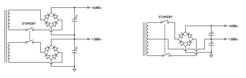
The circuit on the left. If you wire it up like this, into a "Double Bridge Rectifier" ; you will get 600 volts on both rails. I'm not so sure you want 600 volts to the screens. The circuit on the right would be more correct.
-g
______________________________________
Gary Moore
Moore Amplifiication mooreamps@hotmail.com
 Tweet
Tweet

Comment