 Tweet
Tweet
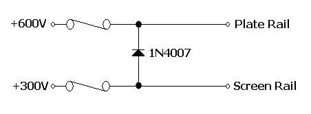
Fusing idea: Install a 1N4007 such that the plate supply draws current from the screen supply (and through the screen supply fuse) when the plate supply fuse blows. The plate supply can never go lower than a diode drop below the screen supply. I see this all the time in test systems with multiple power supplys primarily for analog circuitry.
-
WARNING! Musical Instrument amplifiers contain lethal voltages and can retain them even when unplugged. Refer service to qualified personnel.
REMEMBER: Everybody knows that smokin' ain't allowed in school ! -
Jon Wilder
Wilder Amplification
Originally posted by m-fineOriginally posted by JoeMComment
-
Precisely!WARNING! Musical Instrument amplifiers contain lethal voltages and can retain them even when unplugged. Refer service to qualified personnel.
REMEMBER: Everybody knows that smokin' ain't allowed in school !Comment
-
That's actually quite badass. Wonder why I never thought of that!
Sometimes I need to open my mind a bit more. Thanks for that.
Enough people from this forum continue to contribute ideas to this we're gonna have to call it the MEF Dual Rail.
Jon Wilder
Wilder Amplification
Originally posted by m-fineOriginally posted by JoeMComment
-
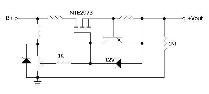
Yes. That will give you a 0V to Vz output, where Vz is the first zener's voltage. The pot should be a high value pot. 1" diameter pots are not rated for a lot of power, and it will dissipate Vz squared divided by the end-to-end pot value. Note that you need to calculate the zener dissipation and resistor dissipation feeding the zener as well. There are a lot ofo volts across them, and you can overheat them with a little current.Originally posted by Wilder Amplification View Post
The low resistance/high power resistor in the source of the MOSFET is there for a number of purposes. it may or may not be needed. I would still connect the 12V zener between source and gate, and the source resistor after that. The 12V zener never conducts except when some transient tries to overvolt the gate, so it's mostly an open circuit except in disasters. The source resistor is where you'd put the base-emitter of an NPN to sample the output current. The resistor is sized to have 0.6V across it and turn on the NPN when the output current needs limited. The collector of the NPN goes to the gate of the MOSFET and steals its drive voltage when the OC limit is reached. If you do it that way, the NPN needs to have a BVceo of greater than the zener voltage or it will lower the output voltage only until its collector breaks over.Amazing!! Who would ever have guessed that someone who villified the evil rich people would begin happily accepting their millions in speaking fees!
Oh, wait! That sounds familiar, somehow.Comment
-
That resistor is a current limit. When the voltage across it reaches the zener voltage minus the gate-source voltage, the current limit kicks in. So it's needed if you want a current limit!Originally posted by Wilder Amplification View PostComment
-
Ah! Nice. Even though I know, I keep forgetting how very high the gate impedance of a MOSFET is. It acts like it's own current limiter by the zener pulling down the gate.Originally posted by Merlinb View Post
The current limit threshold is more poorly defined than you'd get with the base-emitter threshold of a bipolar pulling the gate drive away, but you may not need precision if you can calculate bounds on what happens. And you have lots of volts to play with in this setup.
So to calculate the current threshold, you'd need the min and max threshold voltage, which is probably 2.5-5V for a high voltage MOSFET, and a source resistor which dropped the protection zener voltage minus the threshold voltage at max current. So for a 100ma threshold, you'd select a zener which was large compared to the variation in threshold voltage and small compared to the output voltage, and less than the absolute maximum gate-source voltage to still give protection in the zero current case. Actually, 12V isn't all that bad a choice. 15V would do as well. Then you pick a resistor value of 12V-2.5V = 9.5V divided by the current limit of 0.1A, or 95 ohms.
The disadvantage is that the 95 ohms also appears in series with the output voltage, so it ruins regulation by its drop of up to 9.5V, but that may be acceptable in a 300V regulator; likewise the actual voltage threshold is 9.5 to 12.5V, which gives a current threshold which varies quite a bit, but it still prevents a complete overcurrent.
Quick and dirty current limit on a MOSFET with only a resistor added to the protection zener. I like it!Amazing!! Who would ever have guessed that someone who villified the evil rich people would begin happily accepting their millions in speaking fees!
Oh, wait! That sounds familiar, somehow.Comment
-
Screw it...let's add in the complexity -
 Jon Wilder
Wilder Amplification
Originally posted by m-fineOriginally posted by JoeMComment
-
Wow, this is more advanced than I was looking at. Not that it's bad- it's really good to see how simple it can be to make a current limited supply.
I was only planning a mosfet drain to B+, source to a resistor to ground, gate stopper to a stack of zeners (possibly with a few taps along the way to adjust voltage in steps), resistor from the top of the zeners to B+. If I wanted the screens to sag with B+ I'd use a combination of zeners and a resistive divider or a purely resistive divider. I'd probably use a small value cap from the gate stopper to ground as well.
I built something like this a while back and it worked fine but I never completed an amp with such a design. My inspriration was an old hifi amp that use 3 6L6's- two for output and one as a screen regulator.
jamieComment
-
Let's add in our crowbar for short protection -
 Last edited by Wilder Amplification; 09-10-2010, 05:16 AM.Jon Wilder
Wilder Amplification
Originally posted by m-fineOriginally posted by JoeMComment
-
How does that protect against shorts??Originally posted by Wilder Amplification View Post
If you use current limiting them you will need a much bigger gate stopper, since it is effectively shorted to ground during overload conditions.Comment
-
Thanks for the tip! I figure a 100K 5W should do.
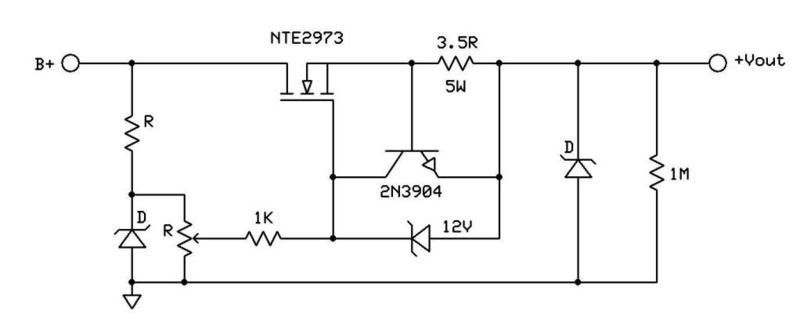
Actually the idea behind the "crowbar zener" is to protect the powered circuit from over voltage in case the pass transistor happens to blow shorted. It's rated at a voltage that is higher than the output voltage but lower than the input voltage so that in the event that the pass transistor blows shorted, it creates a short circuit across the supply so that it will blow the HT fuse and not damage the powered circuit due to over voltage.
The 2N3904 and the 3.5R resistor is set up as a current limit at about 150mA. Since it's for a screen supply you shouldn't need anymore current than that.Last edited by Wilder Amplification; 09-10-2010, 03:10 PM.Jon Wilder
Wilder Amplification
Originally posted by m-fineOriginally posted by JoeMComment
-
When the current is big enough to cause 0.6V to appear across the source resistor, that turns on the NPN. This pulls current through the 1K resistor and shunts it into the output. This causes a voltage drop in the 1K, lowering the Vgs. This cuts the enhancement voltage to the MOSFET, and makes it reduce conduction down to the place where it does not increas current. The current is almost brick-walled at the value which causes the NPN to start conduction. It's a much sharper current limit than the zener, but does the same thing - it steals the gate-source enhancement voltage.Originally posted by Merlinb View Post
Sorry - that's the answer to a question you didn't ask. I read the posts incorrectly. OOps.
Probably not. The NPN limiter looks like a current sink. It's high frequency impedance is high, much higher than the resistor. The resistor remains looking like a resistor. The NPN never quite shorts the Vgs, because even on a dead short on the output, the NPN is pulling just enough current to let the MOSFET provide the same current into a short.If you use current limiting them you will need a much bigger gate stopper, since it is effectively shorted to ground during overload conditions.
The issues with the NPN clamp are
(a) the NPN has to have a high voltage rating so it doesn't break over when you don't want it to
and
(b) dissipation on the MOSFET under short circuit conditions are relatively harsh. It's got the full supply voltage less any resistor dropping losses times the limit current. That's all coming through as heat. If you expect long term shorts, it has to have enough heat sink to work at that dissipation full time.
These are fairly standard linear regulator issues.Last edited by R.G.; 09-10-2010, 03:37 PM.Amazing!! Who would ever have guessed that someone who villified the evil rich people would begin happily accepting their millions in speaking fees!
Oh, wait! That sounds familiar, somehow.Comment
-
The 2N3904 is not enough voltage rating for the NPN. You need a couple of hundred volts there so it doesn't break over. I'll run a version of this in a simulator later today and recommend a transistor.Originally posted by Wilder Amplification View Post
Instead of a zener, use a real crowbar - an SCR. Put the SCR across the real B+, and enough resistance in series with it to ensure the B+ fuse blows but not that the really violent turn on of the SCR will kill your rectifiers and filter caps. Put a resistor across the gate and cathode of the SCR to ensure it doesn't blow upon seeing ghosts 8-) and then put your zener to the regulated voltage. The zener turns on the SCR gate, the SCR pops the B+ fuse in a controlled way. You can use a much cheaper and tighter regulation zener to trip it.Amazing!! Who would ever have guessed that someone who villified the evil rich people would begin happily accepting their millions in speaking fees!
Oh, wait! That sounds familiar, somehow.Comment
-
Belay that stuff about needing a high voltage NPN. I put it on the simulator, and that made me think, which always hurts... 8-)
The power MOSFET, as long as it is operating linearly, starves the source circuit for current so the voltage drops. However, in doing so, the gate of the MOSFET controls how far down it goes, and the MOSFET by its follower action keeps its own gate below a couple of volts above the source. If the gate gets higher than that, more current flows in the MOSFET and raises the source so the gate can't get higher. In addition to the NPN protecting the MOSFET, the MOSFET protects the NPN. Cute.
As long as the MOSFET's alive, the NPN can't get killed, and as long as the NPN is alive, the MOSFET is protected from overcurrents.
A 2N3904 will work OK as a limiter. In the simulation, I ran 400V into a 200V zener string, and used an IRF830 model with an NPN, then applied a varying current load. I used a 5 ohm current limit resistor, and the thing produced limiting as expected.
The 12V zener limiter worked too, with a source resistor of more like 33 ohms. So the "regulation" on the output voltage was sloppier by the difference between the drops on the 5 ohm resistor and the 33 ohm resistor. There is much less limiting gain in the zener circuit, and so it's got a much softer ( I guess that equals sloppier ) entry and exit from limiting, but that may not be an issue for a disaster preventer as long as you can calculate the edge conditions so you can guarantee nothing burns out.Amazing!! Who would ever have guessed that someone who villified the evil rich people would begin happily accepting their millions in speaking fees!
Oh, wait! That sounds familiar, somehow.Comment
Comment