 Tweet
Tweet
Originally posted by mooreamps
View Post
-
i'm pretty sure the left is just a bridge rectified signal floating on another. assuming that one half of the windings will give you 300v then you should get the voltages on the diagram. all he is doing is connecting what would be a ground in the fwb rectifier to a 300v point, floating the voltage on the +ve side 600v. -
Exactly! Although the windings would be 225V each...there's the 1.414 factor involved there. Actual unloaded voltage I calculate at 318 and 636...600 and 300 is what I estimate the loaded voltage to be at with tubes in and biased.Originally posted by black_labb View Post
Mooreamps, look at the two schematics. They're one and the same..the only difference is that the one on the right uses a topology similar to a grounded center tap rectifier whereas the one on the left full wave bridges both windings. The top cap is being charged with a positive voltage while the negative cycles are charging the other, with the center tap as the neutral reference. But since the negative side of the bottom cap is referenced to ground, this references the center tap node to 1/2 the total supply voltage relative to ground, while across both of them you have double the voltage of each cap...just like wiring two batteries in series.
In both scenarios, you have two filter caps in series, and each filter cap is being charged by two separate windings of indentical voltage. Placing the caps in series doubles the voltage of the two windings, just like wiring two batteries of identical voltage in series does. A center tapped HT winding is exactly the same as two separate windings wired in series...but on the center tapped one the windings are internally series wired whereas on the two separate windings the wires that would normally be joined into one internally are brought out of the transformer. If you were to join them together externally, this would be the same as having a single CT wire with the two windings joined internally. Theoretically you could use two bridge rectifiers on a single CT winding and do the exact same thing...6 in one 1/2 dozen in the other.
If you wanna get real technical, they're both dual polarity power supplies, but instead of referencing the 1/2 voltage node to ground, you reference negative supply output to ground, which gives you double the voltage just like if you were to float a DMM across the + and - outputs of a dual polarity supply.
Imaradiostar, that regulator trick is a good one. I might just go ahead and do that during the testing phases just for the sake of being able to experiment with different screen voltages.Last edited by Wilder Amplification; 04-11-2010, 06:49 PM.Jon Wilder
Wilder Amplification
Originally posted by m-fineOriginally posted by JoeMComment
-
Here's the other one I think is really well done. Heyboer could wind you a transformer a lot like this for a reasonable fee:

I thought I'd offer a suggestion to anyone interested. Many large 60's tube o-scopes had transformers that can be used this way. I have a PT from a Knight scope that has two 148 volt windings and one 165 winding- arranged similarly to the Hiwatt schem above I get about 400 volts for screens and around 600 for the plates at enough current to feed 4 KT88's. It weighs about 14 pounds!!
I have another similar transformer in a Heathkit scope that I don't have the heart to destroy yet but I have a hunch, from the voltages, that it'll produce similar voltages and currents with minimum effort.
jamieComment
-
And that brings up the subject of fusing. I see they did in fact fuse the negative, which was the only way I could figure to fuse both supplies with a common HT fuse.
I know standard practice states to fuse the positive. What I'm curious of is if you could fuse the positives of both supplies, but rate the screen fuse low enough to where if the plate fuse blows, screen current will increase enough to take out the screen fuse but not be so low that the screen fuse pops at full rated output. My way of thinking on this is that usually if a plate fuse pops, the tubes are already shot anyway so if screen current goes through the roof just long enough to take the screen fuse out it won't matter anyway since the tubes are more than likely shot at that point anyway and would be why the plate fuse went in the first place.
Of course the other side of me says that you cannot guarantee with 100% certainty that the screen fuse will pop in time every time the plate fuse blows, which leads me to wanna fuse the negative side.
Heyboer has really decent prices. They charged me $106 shipped to wind me the plate tranny I have sitting here with a dual primary and a single HT secondary (non-center tapped) with a 6.3V @ 6A heater winding. In hindsight (which is always 20/20) I should've had them center tap it dual secondary style but didn't think to at the time so I'll probably have to have them wind a 2nd one with that option.
I notice they run the screens on that supply at more than 1/2 the plate. Wonder if there's any real advantage to this or if it'd be a moot effort with diminishing returns. The only thing I'd change on that bias supply is to put a fail safe resistor from the supply node to the wiper so that the tubes don't lose bias in the event of a wiper failure, but not sure if that's really possible with independent bias like that. On the scheme it seems like it would work though.Jon Wilder
Wilder Amplification
Originally posted by m-fineOriginally posted by JoeMComment
-
As Steve mentioned in this thread or last some tubes need higher screen voltage to get the job done. You can safely run EL34's at very high plate voltages with the screens at 1/2 of plate voltage and they'll be OK. 6L6's need a little more screen voltage to make full power- a 3:2 ratio seems to work nicely from circuits I've seen. The KT88 should work nicely with this ratio- as evidenced by the Hiwatt circuit.
Why not just have two HT fuses? (One on each secondary)
I'm really busy with school but if I wasn't I'd set up some test scenarios with the tubes I have on hand just to compare real-world screen and plate voltages and currents and the output power for each. I've been meaning to anyway because I'm trying to get max clean wattage for a bass amp project.
jamieComment
-
Well that's what I'm wanting to do, however if the plate fuse blows you don't want the screens live as screen current will go through the roof. That's why I'd asked if I do a fuse on each supply, if I could rate the screen fuse so that it won't blow at full output or so), but if the plate fuse goes the screen current would increase just enough to take out its fuse. Was thinking a 100mA screen fuse would more than accomplish this?Originally posted by imaradiostar View Post
Unfortunately something tells me I'll never know the real answer to that unless I do some destructive testing, such as pulling out the plate fuse, then taking it out of standby to see if the screen fuse goes.
If I do decide to double fuse, I'll more than likely locate the screen fuse inside the amp since if it blows you've definitely got some real problems and the user shouldn't be able to easily access it to prevent the possibility of them installing the all too common tin foil 1,000 Amp fuse to get through the gig. Jon Wilder
Wilder Amplification
Originally posted by m-fineOriginally posted by JoeMComment
-
I thought about that briefly but didn't think through it far enough to really work that out. I'm sure there must have been ways of dealing with this in the past- surely they didn't crank up an old theater amp without some way of protecting the screens? Oh wait...just looked one up and it used 811 triodes on the output.
The Hiwatt solution with the fuse on the lower part makes sense too- of course if something goes horribly wrong with the bridge rectifier for the upper half of the supply then it could still take out the power transformer. Maybe you could just size the fuses so that the upper half is less likely to go- so that the bottom half would go first, disabling the amp. The top one would be there to protect the secondary or a direct short of the upper rectifier's output.
If you look at some of the really high power amps built by John at Champ Amps he uses fuses all over the place- between the secondaries and the bridges and between the bridges and the load. He also tends to connect a relay across the bias supply so that the screen and plate supplies are disconnected if bias goes away. I suppose it'd be simple enough to wire the screen supply on a relay to disconnect if the plate supply goes away.
I've had some random failures on my lowish power amps and I've been fortunate not to damage power transformers. On a small amp (say 20w or less) with a cheap PT it isn't such a big deal. On a larger amp with many hundreds of dollars of transformers or output tubes it makes sense to fuse everything. You can get a Keystone fuse holder (3ag style, holds 4 fuses) from Mouser for under $4. I figure one external fuse for appearances and a bunch of internal ones should be safe. If for some reason someone blows the external fuse and replaces it with aluminum foil, the internal fuses will still protect the more expensive bits.
So much of what I've built so far has been something on a bench as a proof of concept. I wish I had more finished stuff to share. I guess that's where it's nice to look at someone else's projects to learn and compare.
jamieComment
-
Originally posted by black_labb View Post
Ya, I had to look at it again. you're probably right. you need a single coil secondary for a double-bridge. here he shows a two coil secondary...
-gComment
-
It's really just a "fancier on paper" way of accomplishing the same end result. The benefit to having two separate windings is that by altering the voltage of the screen winding, you can set the screen voltage higher than 1/2 the plate voltage whereas on a single CT winding you're stuck with 1/2 the plate voltage for your screens unless you get the single winding wound as a "not so center" tap.Originally posted by mooreamps View Post
Jon Wilder
Wilder Amplification
Originally posted by m-fineOriginally posted by JoeMComment
-
I know.
-gComment
-
OK this is the finalized design of the first supply I'm going to run.
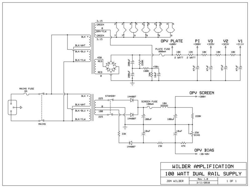
Unfortunately I didn't spec the HT winding to be "double center tapped" (i.e. make two 1/2 voltage HT windings out of the 1) so I have to run it with a separate screen tranny. Originally I didn't think about needing the double winding but in hindsight (which is always 20/20) I see now that I should've had it set up that way right out the gate so that I could try the double winding topology with the same plate tranny.
So more than likely I'm gonna have a second PT wound with everything on it and compare the two to see if there's any difference in the way that the power amp reacts with either or supply. But this supply will be the first one I prototype into this design, then we'll go from there.
Waiting on the screen and output tranny to arrive...having Heyboer wind those...the OT will be a 5K plate-plate with 4/8/16 ohm taps on the secondary.Jon Wilder
Wilder Amplification
Originally posted by m-fineOriginally posted by JoeMComment
-
Looks good. Are you planning to use it mainly with kt88's/6550's? Any reason why you're not running the preamp from the screen TF? Voltage too low?
A thought for you Jon- if you want an off-the-shelf solution that could be really inexpensive. Look at the 400 watt 400 volt antek toroid. It now has 470 and 400 volt taps. You could get a little over 600 volts from the 470 tap using a bridge and a C input filter. Using a 5th and 6th rectifier and a choke input filter you'd get about 350VDC on the 400VAC tap and about 400VDC on the 470VAC tap.
I'm surprised no one commented on the o-scope PT thing- I would have thought someone out there would have tried this by now. I've officially decided I'm going to gut my Heathkit scope (with its crazy tube complement) and use the PT for a 100+ watt tube amp. It's good for about 200 watts of high voltage supply and 80 watts of filaments- more than I'll need!
If you are having a custom PT wound why not go the hiwatt or tube o-scope route? You could have them wind one with a number of taps using the same size wire (same current handling)- then you'd be able to rearrange them as needed. I'm picturing a 120vac primary, a 7 to 9 amp 6.3 volt secondary, a 225 VCT secondary (300vdc, could be CT if needed), and two each 150 (200vdc) and 75 volt (100vdc) secondaries. This would allow, I think, more than enough options to experiment while you figure out what combination you prefer. For example- you could have about 725vdc with half that for screens using it as a 525VCT winding and still have two 75's left over to increase plate or all voltages by 100 volts and have a 75vac tap left to run the bias supply or even mosfet grid drivers on the output- lots of current available. You could connect the windings to a bridge ala hiwatt and get a reasonable screen/preamp supply around 300-400 volts and use the others to run bias and plate supplies. Frankly I don't understand why someone doesn't sell this already!
Or you could buy triode electronics experimenter's PT...but I guess it's only good for 50 watts.
jamieComment
-
Hey Jamie...Originally posted by imaradiostar View Post
Yes the output section will be running KT88s. I'd have to use an OT with a bigger plate load for EL34s. According to my calculations, I'm thinking I'd need an 8K Zp-p to keep from overdissipating, which would only yield about a 65 watt output with a 600V B+.
And yes...running the preamp off the plate supply due to the voltage being too low on the screen tranny. Trying to hit about 380 at the PI. Might run the FX loop off the screen x-former though since it runs on anything from 280-320 and I wouldn't have to use a very large decoupling resistor on it.
Decided to use the C input filter on the screen supply since most conventional guitar amps run the screens off of a C input filter.
635 (rounded off) is what I calculated at the OPV Plate node with 450VAC x 1.414...600 is what I'm estimating with tubes in and biased.
I'll have to look into this one. Do you have a link or a part number for it?Originally posted by imaradiostar
I should in fact have an experimenter's PT wound that I can use for any prototype really. I can use it for prototyping or for that matter, go/no go testing on amps with suspected bad PTs. Would be a useful tool to have around. I have a 50 watt OT here for troubleshooting 50 watters with suspected bad OTs. I should probably order up a 100 watt PT/OT combo that I can use on both 50/100 watters for that and just mismatch one step up for 50 watters on the OT.Jon Wilder
Wilder Amplification
Originally posted by m-fineOriginally posted by JoeMComment
-
get ready to be flooded with links!
Antek PT-
http://www.antekinc.com/pdf/AN-4TK400.pdf
Weber 20-25 watt generic PT with multi taps for a bridge rect-
https://taweber.powweb.com/store/PTGPsch.jpg
Triode elec multi-tap PT-
THE CONVERTIBLE Universal Multi-Tap Power Transformer
Realistically- you don't need any special PT's or OT's to sub into other amps for testing. I'd bet you could keep a Twin reverb PT (lowish B+ since it's intended for SS rect use) around for subbing into 50-100 watt amps and a generic (I have a new sensor one) 50 watt OT. The New Sensor OT has a 4k primary but it's as large as a twin reverb OT so I don't feel bad putting 100 watts through it, even for extended playing.
Weber has lots of transformers with multiple B+ taps, could be helpful.
Transformers get to be such a specific thing anyway- fender, marshall, vox, hiwatt, all mount entirely differently with little overlap! It's amazing the projects I now have sitting still because I'm unwilling to butcher a chassis for a larger PT or use a normal PT on a z-mount chassis. If you're prototyping your own stuff I guess it doesn't matter but it is nice to be able to show even a bare chassis to someone and have it look decent.
A big part of my decision to gut the old tube scope is to use up an old chassis that had an unusual z-mount PT size which happens to match the scope PT.
I still need to find a source for endbells though- I have a few PT's that would be more usefull if the wires didn't stick straight out the top of the endbell!
jamieComment
-
You might wanna check with Mercury Magnetics...I believe they source end bells.Originally posted by imaradiostar View Post
Yeah I'm not into hacking up chassis myself. Quite honestly I'm debating on whether or not to use Z or X mount on the final model of this amp. The proto trannys are X mount. What's funny about the two is that Z mount looks better from the top than X mount, yet X mount looks better than Z mount from the inside of the chassis lol.
The other advantage to Z mount is that you can go phatter on the iron stack without having to oversize the footprint.
On that Altec toroid...if I decide to build a rack version of this power amp (seriously considering doing up a stereo 100 watt) that would be the perfect candidate for that.Last edited by Wilder Amplification; 04-14-2010, 05:20 AM.Jon Wilder
Wilder Amplification
Originally posted by m-fineOriginally posted by JoeMComment
Comment