Announcement

Collapse
No announcement yet.

The Official Dual Rail Thread

Collapse
X
 
  • Filter
  • Time
  • Show
Clear All
new posts

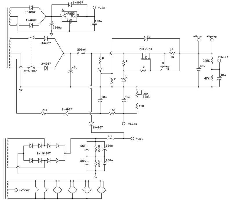
  • OK...here's the scheme I've come up with for the Dual Rail PSU utilizing the transformers I originally had wound for this thing. Included pretty much every idea from this thread in it. Anything else that we feel needs to be added feel free to contribute.

    A bit overengineered?

    Jon Wilder
    Wilder Amplification

    Originally posted by m-fine
    I don't know about you, but I find it a LOT easier to change a capacitor than to actually learn how to play well
    Originally posted by JoeM
    I doubt if any of my favorite players even own a soldering iron.

    Comment


    • Originally posted by Wilder Amplification View Post
      A bit overengineered?
      Overengineered? Bah!

      Under-profundicated.

      A couple of notes. You may want to put a power resistor in series with the high voltage diodes to soften the B+ supply a bit and cut down on transformer heating, at the cost of sloppier B+ voltage. And you may want to worry a bit about series connecting 1N4007s. Yes, you often get away with it, but if the capacitive parasitics aren't nearly equal, one diode can wind up supporting the entire voltage for a few microseconds while the parasitic cap voltages equalize and that can break otherwise good devices. Swamping the parasitics with equal-valued ceramic disc caps parallel with each 1N4007 forces dynamic equalization, and helps with the RF noise caused as ordinary recovery diodes snap off in recovery from conduction. Or you may want to use UF4007s, which are fast recovery. They still can die from capacitive imbalance if the voltage across them approaches 1.5-1.8 times the breakover voltage.
      Amazing!! Who would ever have guessed that someone who villified the evil rich people would begin happily accepting their millions in speaking fees!

      Oh, wait! That sounds familiar, somehow.

      Comment


      • Noted.

        BTW I like that SCR w/series resistor idea. No need to create a dead short...just a load low enough to draw the required current to take out the fuse so that the crowbar isn't so violent.
        Jon Wilder
        Wilder Amplification

        Originally posted by m-fine
        I don't know about you, but I find it a LOT easier to change a capacitor than to actually learn how to play well
        Originally posted by JoeM
        I doubt if any of my favorite players even own a soldering iron.

        Comment


        • Originally posted by Wilder Amplification View Post

          A bit overengineered?
          I'm sure the schematic is correct and I'm sure it will operate as intended. Personally, I've not had to use a series FET to get good regulation from my Split Rail HV supply. Full load on my +600 volt rail and +300 volt rail with about 200 millivolts rms of ripple was done using a shunt regulator ; only these parts : two 450 volt 47 uF filter caps wired in series ; two UL LED ; and two bias resistors for the leds. Perhaps this circuit is "under engineered", but it's simple to setup and works well enough. Plus I get the attack on the note when using the smaller value filter caps...

          Getting back to your series FET, it may need a heatsink. The VVR does.....

          -g
          ______________________________________
          Gary Moore
          Moore Amplifiication
          mooreamps@hotmail.com

          Comment


          • Originally posted by mooreamps View Post
            Personally, I've not had to use a series FET to get good regulation from my Split Rail HV supply. Full load on my +600 volt rail and +300 volt rail with about 200 millivolts rms of ripple was done using a shunt regulator ;
            Shunt regulators work, but they're complex to design to ensure that they work under all conditions. Simple shunt regulators with zeners are OK for low-power applications, but IMHO are disasters for any significant power. I've seen too many instances of zener designs dying or having the series resistor get hot enough to char the PCB and/or melt the solder off it's connections.

            Choosing shunt regulation over series regulation is a design choice. The choices get involved where long term reliability is an issue.

            only these parts : two 450 volt 47 uF filter caps wired in series ; two UL LED ; and two bias resistors for the leds.
            Just off hand, it's not clear how two LEDs could be made into a 300V regulator, if that's what you're describing. Can you explain how that works?

            Getting back to your series FET, it may need a heatsink. The VVR does.....
            Math is our friend. Once you know the voltage across the device and the max current out, which you can simply set by the current clamp values, and have selected a value for the series dropping resistor, you can calculate the FET dissipation for any loading, as well as the resistor dissipation. The FET will have specified the max dissipation it can stand, as well as the thermal resistance from junction to case, and probably the free air thermal resistance of just the case. From there on, it's a matter of totaling up the dissipation estimate, applying that to the thermal resistance to get temperature rise at the junction and coming up with a heat sink thermal resistance low enough to keep the junction under Tmax, given the maximum ambient temperature you design for.

            It's not clear what you mean by "VVR". A quick look at acronyms on the web gives the following possible meanings:
            VVR Verkehrsverbund Rottweil GmbH (German)
            VVR Voltage Variable Resistor
            VVR VSAM Volume Record (IBM mainframes disk storage management)
            VVR Vicks Vapor Rub (cold relief product)
            VVR Vintage Vee Racing
            VVR Vision Video Recorder
            VVR Veterans Volunteer Reserve (Manitoba, Canada)

            Presumably it's an electronic part, so voltage variable resistor seems like the most likely, but you didn't mention a voltage variable resistor. I guess that gets back to the question of how your circuit regulates with two filter caps, two LEDs and two bias resistors. Could you 'splain that a little?
            Amazing!! Who would ever have guessed that someone who villified the evil rich people would begin happily accepting their millions in speaking fees!

            Oh, wait! That sounds familiar, somehow.

            Comment


            • Originally posted by R.G. View Post
              It's not clear what you mean by "VVR".
              He means Variable Voltage Regulator. It's become a common acronym on these boards, for the various series FET voltage stabiliser circuits used for amp power reduction.

              Comment


              • Right...Variable Voltage Regulator. The power scaling crowd is damn near in love with it.
                Jon Wilder
                Wilder Amplification

                Originally posted by m-fine
                I don't know about you, but I find it a LOT easier to change a capacitor than to actually learn how to play well
                Originally posted by JoeM
                I doubt if any of my favorite players even own a soldering iron.

                Comment


                • Ah. Ok. That's one I didn't know. I don't follow the power scaling stuff.

                  So, back at the question: how does one make a variable voltage regulator out of two caps, two resistors and two LEDs?

                  Gary?
                  Amazing!! Who would ever have guessed that someone who villified the evil rich people would begin happily accepting their millions in speaking fees!

                  Oh, wait! That sounds familiar, somehow.

                  Comment


                  • I've been away from here for months, is this thread still going?!

                    If you search Gary's old posts, you'll see that his power scaling system, as far as I know, is just a variable resistor in series with the power tube screen supply. If that's untrue, Gary, I apologize for putting words in your mouth, but at least it had words in it that made sense for a while.

                    I liked his idea enough that I tried it in my latest amp. (Along with a lot of other things that would make people think I had gone as mad as Gary. ) However, I chose to use the pot as a voltage divider between B+ and ground, and buffered the voltage with a TO-220 MOSFET.

                    Issues in "VVR" circuits are:

                    To regulate or to capacitance multiply?

                    What's the required voltage and power rating of your voltage adjust pot? All of the simple power scaling circuits I've seen just whack the whole rail voltage across this pot. I did that too for simplicity, but I used a huge old 1 Meg carbon one that looked like it could take it. The high resistance means that the pot's power rating isn't exceeded, and the MOSFET gives it enough Oomph to drive the screen supply.

                    How big a MOSFET do you need? (Gary's original system doesn't need one at all.)

                    What do you vary, plate voltage, screen voltage, preamp voltage, or some combination of the three?

                    How do you get the bias to track the screen voltage in a fixed bias amp? (In a cathode bias amp, it tracks automatically.)

                    Can you protect the MOSFET from dying in the event of a tube short? A fuse won't necessarily save it. (If you're a hobbyist it probably doesn't matter. You built the amp so it probably won't trouble you to change the MOSFET.)

                    etc.
                    Last edited by Steve Conner; 09-13-2010, 01:58 PM.
                    "Enzo, I see that you replied parasitic oscillations. Is that a hypothesis? Or is that your amazing metal band I should check out?"

                    Comment


                    • Steve! Glad to see ya back!

                      Yep it's still going...I haven't had time to build it over the last few months but I'm starting to get back on the project again. Now that we've decided to go with fully regulated screens I'm gonna need a few more parts to do the final version.

                      As soon as I finish my over engineered transistor relay driver in my personal high gain amp I'm gonna start mounting stuff onto a chassis and wiring things up to test it and get some numbers.

                      Now here I was thinking about using a VVR circuit to scale the screen voltage up a little higher in the event that the power output was too low (load line on paper crosses through the knee rather than below it currently) when all of a sudden it hit me the other day...I have a damn Variac! So during testing just to get the numbers I'm gonna hook the screen tranny up to the Variac and scale the screen voltage up that way if I need to.

                      But the final version of the amp will have a fixed regulator on the screens. I'm planning on using an NTE2973 unless people here happen to know of a better MOSFET to use for the job.
                      Jon Wilder
                      Wilder Amplification

                      Originally posted by m-fine
                      I don't know about you, but I find it a LOT easier to change a capacitor than to actually learn how to play well
                      Originally posted by JoeM
                      I doubt if any of my favorite players even own a soldering iron.

                      Comment


                      • Originally posted by R.G. View Post
                        Ah. Ok. That's one I didn't know. I don't follow the power scaling stuff.

                        So, back at the question: how does one make a variable voltage regulator out of two caps, two resistors and two LEDs?

                        Gary?

                        I did not mean to say it was variable. I was trying to say it had good ripple rejection.

                        I don't follow the power scaling stuff either. I never did like the idea of putting a regulator of any type on the plate rail.

                        -g
                        Last edited by mooreamps; 09-13-2010, 02:44 PM.
                        ______________________________________
                        Gary Moore
                        Moore Amplifiication
                        mooreamps@hotmail.com

                        Comment


                        • Originally posted by Steve Conner View Post
                          I've been away from here for months, is this thread still going?!

                          If you search Gary's old posts, you'll see that his power scaling system, as far as I know, is just a variable resistor in series with the power tube screen supply. If that's untrue, Gary, I apologize for putting words in your mouth, but at least it had words in it that made sense for a while.
                          It's actually in parallel with the screen supply. I get away with it because the power dissipation is so low, and I figured out how to bypass the wiper on the pot to make it work, well work good enough.. It will still throddle down the plate current on the power tubes, which at the time, was my understanding of what it was supposed to do. I came up with the circuit while waiting for kevin's TUT4 to come out at the time, not knowing what he was going to do with it.


                          -g
                          ______________________________________
                          Gary Moore
                          Moore Amplifiication
                          mooreamps@hotmail.com

                          Comment


                          • Ok... Well, I liked your general idea, that you could do power scaling simply by varying the screen voltage on a cathode biased amp. I tried it, and it worked for me. The tone changed a bit at lower screen voltages, but that didn't strike me as a bad thing.

                            And, hi to Jon and everyone else! I've been super busy on our next product, so I haven't had much time for net surfing. Jon, I think Enzo said never to buy anything NTE. MOSFETs over 600V are quite expensive and hard to find. My favourite big MOSFET is the IRFP460, but it's 500V.
                            "Enzo, I see that you replied parasitic oscillations. Is that a hypothesis? Or is that your amazing metal band I should check out?"

                            Comment


                            • Originally posted by Steve Conner View Post
                              Jon, I think Enzo said never to buy anything NTE. MOSFETs over 600V are quite expensive and hard to find. My favourite big MOSFET is the IRFP460, but it's 500V.
                              Enzo was right about NTE. Buying NTE is the kind of thing you do behind closed doors and wash your hands afterwards. 8-)

                              I just checked my favorite supplier here in the states. Mouser Electronics lists 22 power MOSFETs with voltages between 800 and 1000 in a TO-220 package for $2.00 each or less. The Fairchild FQPF6N80CT is 800V, 5.5A, 51W rated, and costs $1.01 each in ones; the full-pack insulated version is $1.10. The cheapest 1KV one is the IXYS IXTP05N100 for $2.13.

                              On your earlier question Steve:
                              Can you protect the MOSFET from dying in the event of a tube short? A fuse won't necessarily save it. (If you're a hobbyist it probably doesn't matter. You built the amp so it probably won't trouble you to change the MOSFET.)
                              MOSFETs will die from either overvoltage or overdissipation, since second breakdown doesn't occur, or from gate damage. You protect them from gate transients with a combination of the gate stopper and gate clamp diodes. You protect them from overvoltage by picking a device with enough voltage and with reverse clamping diodes. You protect them from overdissipation with a calculator. 8-)

                              It's not too difficult to put a current clamp in there that will limit B+ to under 5A (using the cheap MOSFET above as a model) and use a B+ fuse that's down around half to one amp. A 5:1 overcurrent blows that fuse pretty promptly. The issue then is just whether the MOSFET survives the power dissipation for the most likely time to blow the fuse. The raw dissipation is 51W for that model device, so there's a chance if it's properly heat-sunk, or simply connected to a big enough thermal inertia so that the time to blow the fuse won't let the junction temps get destructive. Another alternative is to put in a foldback current limit or a volt-amp limiter to limit the dissipation on it as well.

                              It takes some decent design work, but it's by no means impossible.
                              Last edited by R.G.; 09-13-2010, 04:09 PM.
                              Amazing!! Who would ever have guessed that someone who villified the evil rich people would begin happily accepting their millions in speaking fees!

                              Oh, wait! That sounds familiar, somehow.

                              Comment


                              • Originally posted by R.G. View Post
                                MOSFETs will die from either overvoltage or overdissipation, since second breakdown doesn't occur
                                That's an old electronics industry myth. MOSFETs do have a failure mode similar to second breakdown, caused by the negative tempco of Vgs at low currents and high voltages.

                                No MOSFET is specified for linear use at low current and high voltage, except for some from APT, and Ixys' new Linear L2 series. This means that all of these "VVR" circuits depend on unspecified behaviour of the device. They're cool for hobbyist use, but if I was taking one into production, I'd use the Ixys Linear L2 devices.

                                And they don't come over 600V, another piece of evidence that makes me think the problem would be even worse with higher voltage devices.
                                "Enzo, I see that you replied parasitic oscillations. Is that a hypothesis? Or is that your amazing metal band I should check out?"

                                Comment

                                Working...
                                X