Ad Widget

Collapse

Announcement

Collapse
No announcement yet.

The Official Dual Rail Thread

Collapse
X
 
  • Filter
  • Time
  • Show
Clear All
new posts

  • #76
    Originally posted by Wilder Amplification View Post
    And this is EXACTLY why I never got into the engineering and mathematical side of this shit for the longest time...because you can't calculate tone!!! lol
    Weeeell.....

    If you plot enough loadlines for amps which are considered to have good tone, you do start to notice patterns, such as the OT load line always passing somewhere below the knee, and you can start to predict the levels of grid current in a preamp triode, for example, and so estimate the value of grid stopper, or whether a cathode bypass cap would be a bad idea etc. So you can't calculate tone, but there are links between the graphical and the tonal, and load lines remain the most powerful analysis tool available (better than SIM, IMO).

    Comment


    • #77
      I would like to ask a question, before opening (maybe) a new thread on the amp I'm designing.

      How do you calculate the current rating of the PT secondary windings for a "dual rail" supply (ala Hiwatt 200)? As I understand, most of the DC plate current (higher than idle current on maximum power, since we're talking class AB) flows in the screen power supply, so I have to specify at least the same current for both secondaries?

      Thanks in advance for the reply.

      Comment


      • #78
        I'll hazard a guess...

        The top winding needs to be spec'd for max plate current.

        The lower winding needs to be spec'd for max plate current plus screen current plus preamp supply. If you spec conservatively- I'd follow the datasheet values for plate and screen current, add a fair margin and look for 5% regulation.

        In the real world on production amps it's much less likely that you'll find a transformer with specs that good. Hiwatt is probably an exception though- I haven't been inside an old one but people that have claim the transformers are very high quality and have excellent regulation. I was inside a very high quality US made clone but it was a 100 watt model, not a 200 watter.

        Hopefully John will report back about his design soon- he should have some practical experience.

        I've found that the transformers I have tend to have the same gauge wire for each of the high tension windings- they seem to sag and heat equally in series. The screen and preamp current are usually small in comparison to the plate current so I doubt that it will be a problem in the real world unless the amp is run with constant output section distortion all the time.

        jamie

        Comment


        • #79
          OK I'm firing this thread back up as I now have some time to get back into the Dual Rail project. I've pretty much got everything I need to build the power amp...iron, filter caps, ceramic sockets, PI components, etc etc.

          The first phase will be just the power amp itself. I'm gonna use the preamp from another amp out from the FX loop send to drive it for tone testing.

          However, I'm in need of a 27" x 8" x 2.5" chassis blank. Anyone know of a source for blank chassis of that size or a good place to get one custom made?

          As I'm looking at my load line for this amp it appears that I may need to scale the screen voltage up another 50V or so to shift the grid curves up in order to maximize voltage swing to the load on a 5K Zp-p load impedance (load line crosses right through the knee rather than just below it). Of course I won't know until it's running and I can scope and measure the output but on paper this appears to be the case. I have another PT that I can make a temp screen supply from that will have more voltage than I'll need for that, then I can build a VVR circuit using an NTE2377 enhancement mode MOSFET to allow me to scale it down.
          Jon Wilder
          Wilder Amplification

          Originally posted by m-fine
          I don't know about you, but I find it a LOT easier to change a capacitor than to actually learn how to play well
          Originally posted by JoeM
          I doubt if any of my favorite players even own a soldering iron.

          Comment


          • #80
            Originally posted by Wilder Amplification View Post
            And this is EXACTLY why I never got into the engineering and mathematical side of this shit for the longest time...because you can't calculate tone!!! lol
            The math isn't that hard.. But I would keep an eye on your plate dissipation when you bring up your power tubes to idle.


            Originally posted by Wilder Amplification View Post


            I'll have to try it with a 1 step up mismatch...the whole thing looks very good on paper, but as we all know, in the end it's all about how it all sounds, not how it looks on paper.
            I did not use any mismatches on my SE 36. I don't think you will be disappointed.... In fact, as I am in the process of bringing up my mixed mode IPA power tube circuit driver circuit, I could run it at +600 volts verses +300 volts. I should know how that goes in the following week or two.

            -g
            ______________________________________
            Gary Moore
            Moore Amplifiication
            mooreamps@hotmail.com

            Comment


            • #81
              I'm excited to hear how it goes.

              As for the chassis- I've been purchasing aluminum from yarde metals "drop zone" and folding it into a "c" shaped channel then boxing out the ends with either wood or aluminum extrusions from mcmaster.com. You can cut the aluminum easily on a table saw with a carbide blade. If you use the aluminum ends you can have them tig welded in for max strength or just bolt them in.

              jamie

              Comment


              • #82
                As for the chassis- I've been purchasing aluminum from yarde metals "drop zone" and folding it into a "c" shaped channel
                I've done the same thing with 16g steel. For a prototyping chassis, it's perfect, but then again, I build prototype layouts using copper plated nails and poplar or plywood. But any local sheet metal shop will be able to make a chassis for you. It ain't called a box and pan brake for nothing - and our chassis are just glorified pans.

                So just to recap, you're doing 2 x KT-88, 600v plate, 300v screen, 5k primary load, class AB1?
                -Mike

                Comment


                • #83
                  Originally posted by defaced View Post
                  So just to recap, you're doing 2 x KT-88, 600v plate, 300v screen, 5k primary load, class AB1?
                  That is correct. However, using a Svetlana/Winged =C= plate characteristic curves chart with the curves shown at Vg2 = 300V, it appears that a 5K primary load line crosses right through the knee of the Vg1=0V curve, which means I might have to scale the screen voltage up 50V or so to maximize plate drop/voltage swing across the load for maximum power transfer. I have several power transformers laying around with more voltage than I need that I can use a VVR circuit on to scale it down to where I need it if need be for prototyping purposes.
                  Jon Wilder
                  Wilder Amplification

                  Originally posted by m-fine
                  I don't know about you, but I find it a LOT easier to change a capacitor than to actually learn how to play well
                  Originally posted by JoeM
                  I doubt if any of my favorite players even own a soldering iron.

                  Comment


                  • #84
                    Originally posted by Merlinb View Post
                    (I bet it turns out that you like it better with a 16 ohm speaker on the 8 ohm tap )
                    I bet I already built a few already, and I'd bet it don't make a hill a beans worth of difference.

                    -g
                    ______________________________________
                    Gary Moore
                    Moore Amplifiication
                    mooreamps@hotmail.com

                    Comment


                    • #85
                      I just gave a quick read to this thread, and it brought up a couple of stray points in my head.

                      Unless the idea is to NOT use anything newer than about 1965, it's often more conceptually simple and cheaper to use more electronic complexity.

                      In the case of a lower screen supply, you can just regulate the screen supply from a larger plate supply instead of messing with special transformers and rectification. I'm aware of the deep avoidance of active electronics beyond tubes in guitar amps, but it's pretty simple to make a low (in the overall scheme of things) current regulator for the screens which would give you a screen voltage that is (a) adjustable for experimentation, although that's not the major issue in production, and (b) anywhere between rock solid, fixed voltage and saggy, droopy under loading, even tracking to any desired degree with the plate voltage. This could be as simple as a zener stack, a MOSFET or power transistor, and a few Rs and Cs.

                      In the case of fusing and coordinated shutdown, doing the screen supply from a regulated plate supply solves the fusing with a single fuse. However, if you went ahead with dual independent power supplies, it's fairly simple to use a large power MOSFET in the return line to open when an overcurrent is sensed. Or two MOSFETs synchronized by a single signal. Or other conditions to tell them what to do. It's more complex in using more parts, but vastly more predictable in operation. Calculating what lives and what dies when a fuse is the protection mechanism is involved.

                      I know of the deep suspicion in which tube amp builders hold solid state add-ons. But I have personally used both of these paths before in tube amps, and they work. They're other design options for you to use in optimizing cost versus performance.
                      Amazing!! Who would ever have guessed that someone who villified the evil rich people would begin happily accepting their millions in speaking fees!

                      Oh, wait! That sounds familiar, somehow.

                      Comment


                      • #86
                        RG...as I've (don't laugh) JUST RECENTLY started delving into the realm of solid state electronics I'm highly interested in implementing SS control devices such as the ones you mention. Like everyone else I'm not wanting to use SS in the signal path...but SS does a superb job for any sort of "control circuitry". I've already been toying around with the idea of ditching the screen supply choke in favor of a MOSFET regulated screen supply...although this prototype will initially use a separate screen transformer since I've already had the iron made.

                        My way of thinking on using two PTs was to keep the screens completely isolated from the plate supply so that the screen voltage wasn't at the mercy of the plate tranny should the plate circuit start drawing enough current to sag its PT. But the dual PT approach isn't set in stone...I'm wanting to eventually try all of the dual rail psu possibilities and see what differences I notice. Ideally if there's not much of a difference worth mentioning at high volumes I plan to use a single PT on the final version.

                        Any insight and information you can give me on your SS approaches to this would be greatly appreciated. But don't get offended if I start reinventing the 200+year old laws and theories in the learning process.
                        Jon Wilder
                        Wilder Amplification

                        Originally posted by m-fine
                        I don't know about you, but I find it a LOT easier to change a capacitor than to actually learn how to play well
                        Originally posted by JoeM
                        I doubt if any of my favorite players even own a soldering iron.

                        Comment


                        • #87
                          Originally posted by Wilder Amplification View Post
                          RG...as I've (don't laugh) JUST RECENTLY started delving into the realm of solid state electronics I'm highly interested in implementing SS control devices such as the ones you mention.
                          No laughing from this side. Tubes were just out of fashion when I started learning electronics, so I had to go learn tubes remedially.

                          Like everyone else I'm not wanting to use SS in the signal path.
                          I'm addicted to "Mythbusters", and in that vein, I take a "show me" attitude to most engrained items of "common knowledge". I also am very fond of finding out about old technologies, what they did and why. For instance, I can make a serviceable arrow or spear point from flint, or make hide glue. There are good and bad applications to every technology, and what makes me happy is understanding the limits and why those limits apply.

                          So with that long winded prelude, not wanting to use SS anywhere in the signal path is an unfounded taboo. There are places where you can use SS devices for signal in a tube amp without somehow contaminating the audio. That was the thrust of my "MOSFET Follies" article. A high voltage MOSFET makes a dynamite follower that is impossible to detect by ear (and I've asked other people with better ears than mine) and saves you a triode section for gain. MOSFET followers let you go to Class AB2 for driving the devil out of your power tube grids. You just have to know and be careful of the input impedance including the gate-source capacitance and what happens before it clips. If the MOSFET never clips and the gate-souce capacitance isn't a factor, it is *very* difficult to even detect that it's there except for the good it does.

                          But enough preaching. You have a good attitude about this, and I encourage you to keep it open, even to some new signal possibilities. Could be useful. Use your ears and see.

                          My way of thinking on using two PTs was to keep the screens completely isolated from the plate supply so that the screen voltage wasn't at the mercy of the plate tranny should the plate circuit start drawing enough current to sag its PT.
                          A regulated screen supply can do that for you. In the guitar amp biz, people often equate "regulated" with "ugly, nasty, sterile, harsh, solid state". What they fail to realize is that all regulators are special purpose DC amplifiers. They do what you tell them to do. If you tell them to be rock solid, they (usually!) are. If you tell them to sag a bit by adding in a "sag" control signal, they do. If you tell them to have an output impedance other than nearly zero, they do. The limits are that your "regulator" circuitry has to not run out of available voltage to work from and not overcurrent or overheat. Trying to make about half of a B+ supply with a couple of hundred volts of headroom is duck soup - you'll never run out of headroom. The issue is probably overheating, and you can solve that with some resistors between the B+ side to eat up some of the big voltage drop.

                          But the dual PT approach isn't set in stone...I'm wanting to eventually try all of the dual rail psu possibilities and see what differences I notice. Ideally if there's not much of a difference worth mentioning at high volumes I plan to use a single PT on the final version.
                          Even if you don't use it in the final, a regulated screen supply to let you dial in the screen voltage and listen might be interesting, I think, during the design process. I have an old HP power supply that is a tube development lab supply. It has as outputs a 0-400V plate supply, a 0-400V low current screen supply and a filament supply, all in one rackmount box. Neat toy.

                          Any insight and information you can give me on your SS approaches to this would be greatly appreciated. But don't get offended if I start reinventing the 200+year old laws and theories in the learning process.
                          I'm not offended. My mantra is "if it works, use it". But I've found enough places where people told me "Here be dragons" that whenever someone says that, I think they have not actually gone and seen the dragons they think are there.

                          And in any case, reinventing is good. Keep an open mind, think about what you want and use the best method to get to it - where "best" means your choice of the mixture of cheapest, highest performance, easiest to implement, most acceptable to customers, etc.
                          Amazing!! Who would ever have guessed that someone who villified the evil rich people would begin happily accepting their millions in speaking fees!

                          Oh, wait! That sounds familiar, somehow.

                          Comment


                          • #88
                            It's interesting to see the conversation head in this direction. I recently decided to try these ideas and I purchased some high voltage mosfets and an assortment of zener diodes with the thought that I could use them for a regulated screen supply. I haven't built anything yet but I think it should be easy to do so.

                            Of course- I like the idea of a split supply because you don't have to waste energy as heat in a mosfet. I guess wasting energy shouldn't be a design consideration when you're building a tube amp!

                            JT

                            Comment


                            • #89
                              Originally posted by imaradiostar View Post
                              It's interesting to see the conversation head in this direction. I recently decided to try these ideas and I purchased some high voltage mosfets and an assortment of zener diodes with the thought that I could use them for a regulated screen supply. I haven't built anything yet but I think it should be easy to do so.
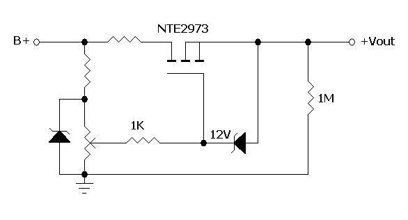
                              The simple thing to do is to make a zener-controlled output. You put a resistor from B+ to a zener to ground. Make the zener be (close to) the voltage you want out, and compute the resistor to keep the zener supplied with enough current for all the reasonable variations of the B+ under sag and high line. You then (subject to the cautions I'll talk about later) connect the MOSFET drain to B+, gate to the top of the zener, and source to the screen supply. The MOSFET source will be one Vthreshold below the zener; that's probably 3-4V. That source voltage will remain almost constant over big variations of the B+.

                              There is an additional bit of circuitry to keep the MOSFET healthy and happy. You need a 1K or so "gate stopper" on the MOSFET gate to keep it from oscillating at VHF or higher. You need a 12V (about) zener from gate to source to prevent transients from zapping the gate. A 1M to ground from the source would help keeping the source voltage well defined in all circumstances.

                              From there you can elaborate. Using two zeners for the reference voltage lets you put a pot across the top one and connect the wiper to the MOSFET gate stopper. Now you can dial in the source voltage you want within the pot range. The MOSFET gate looks like a plate of glass 20V thick so it pulls no current.

                              You can also stick a resistor between drain and B+, and calculate the value so that the resistor drops almost all of the voltage between B+ and the screen voltage at highest screen current. This does not change the total power eaten by the MOSFET +resistor, but shifts it from MOSFET to resistor where power dissipation is cheaper to get and more reliable. You can substantially lower the MOSFET heatsinking needs (if any!) this way.


                              Of course- I like the idea of a split supply because you don't have to waste energy as heat in a mosfet. I guess wasting energy shouldn't be a design consideration when you're building a tube amp!
                              Energy budgets are slippery things. A split supply has its own losses and costs in rectifiers and filter caps. And everything depends on how much current goes into your screens. If that's small, you're only wasting the difference between the B+ and screen voltage times the current. That may be negligible. I don't know how hard you run your screens.

                              Another interesting sidelight to this is that screen dissipation is a killer of tubes at some conditions of overdrive. That's why screen resistors are there, to limit the screen dissipation by dropping screen voltage if a lot of current comes through. You could maybe do some clever work by putting in a current limiter on the MOSFET screen regulator so it provided a constant(ish) screen voltage right up to the point where the tubes would start to die, then limit the current so that the screen voltage goes down there. I'm not sure how that would sound, but it's cheap and easy to implement with resistor and transistor current clamp on the source of the MOSFET.

                              And that's kinda my view on SS in tube amps. Tubes are valuable for the sound they give, and also a limited resource. SS is cheap and very capable. We oughta look for ways to use SS slaves to make the world safer and better for the valuable tubes and the sound they make. Less waste than tossing out tubes we've killed, right?
                              Amazing!! Who would ever have guessed that someone who villified the evil rich people would begin happily accepting their millions in speaking fees!

                              Oh, wait! That sounds familiar, somehow.

                              Comment


                              • #90
                                So basically something like this?


                                I've seen a similar circuit, but they usually use a low wattage high value resistor between the 12V zener and the source. Is that resistor really needed?
                                Jon Wilder
                                Wilder Amplification

                                Originally posted by m-fine
                                I don't know about you, but I find it a LOT easier to change a capacitor than to actually learn how to play well
                                Originally posted by JoeM
                                I doubt if any of my favorite players even own a soldering iron.

                                Comment

                                Working...
                                X